Counterweights often get a bad reputation as clunky and inconvenient. But for perfect visual observations it is great to be able to easily push the telescope around in a completely smooth way. Correct and smart use of counterweights can improve the quality of your observations.
New mounts like strainwave designs can operate with little or no counterweight, but this comes with hidden costs that affect both comfort and precision.
Why Counterweights Matter
A telescope system functions like a lever. Counterweights balance the system, enabling:
Effortless movement – Light set clutches make manual pointing and tracking smooth. On many strainwave mounts, manual movement is impossible, which can make visual observing less enjoyable.
Better tracking and reduced stress – A balanced system reduces wear on gears and motors, improves tracking consistency, and decreases the mechanical strain on the mount.
Improved pointing and stability – Even a well-built stiff mount will experience flexure. The tripod will see changing loads leading to flexure and changing contact to the ground.
Proper balance minimizes these effects, ensuring the telescope stays aligned and pointing remains accurate as well as polar alignment.
Safety and security – An unbalanced system risks tipping the entire tripod, mount, and telescope when the mount slews and load shifts. It can also suddenly swing if brakes are released accidentally or during a power loss, potentially causing damage or injury.
Without counterweights, clutches must often be tightened hard, flexure increases, and the mount experiences added strain. While astrophotography software can compensate to some degree through plate solving and guiding, visual observing provides no such correction, making balance crucial.
Balancing an Alt-Az Mount for perfect visual observations
When balancing an Alt-Az mount only the altitude axis has to be considered. The vertical Azimuth axle is always balanced when it comes to rotation, but remember to keep an eye on the risk of tipping the mount when adding a heavy telescope to one side of the mount head.
Side-Mounted Telescope
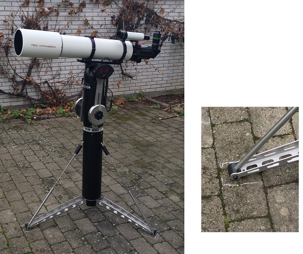
Alt-Az mount with side mounted telescope is the most common design.
Place the telescope horizontal and slide the dovetail plate in the saddle until it is lengthwise balanced.
Tilt the telescope to a near-vertical position and adjust the counterweight to achieve vertical balance.
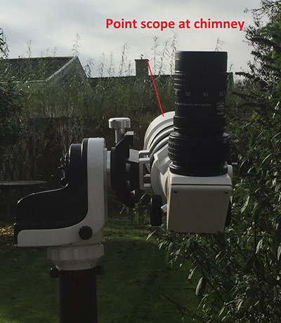
Many mounts do not provide a way to balance vertically (sometimes called Y-axis balancing), meaning the telescope may slide away when pointing high in the sky. Accessories like finder scopes and eyepieces shift the balance away from the OTA center, making vertical balancing essential. This issue becomes more pronounced with heavier eyepieces or binoviewers.
Top-Mounted Telescope
Place the telescope horizontal and slide the dovetail plate in the saddle until lengthwise balanced. Enjoy the horizontal saddle making the adjustment safe and easy.
Tilt the telescope to near vertical and move counterweights on the arms until balanced.
Top-mounted setups must have vertical balancing, as the telescope is away from the altitude axis and will exert more leverage on the mount. All installed accessories are balanced in the same process.
Comfort Balancing
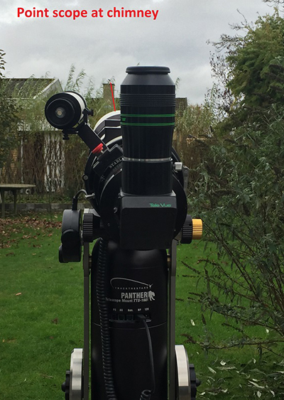
The TTS160 Panther Lite mount introduces a clever feature called “comfort balancing”, designed to reduce eyepiece movement by up to 30cm as object elevation changes.
The system works by using a counterweight on a shaft connected to the altitude axle. By adjusting this counterweight and sliding the telescope forward, the eyepiece can be brought closer to the mount’s rotation center. This makes observing objects high in the sky more comfortable and maintains a good viewing posture for objects near the horizon.
Another advantage is when swapping heavy eyepieces: instead of moving the entire OTA in the dovetail saddle, the counterweight can be shifted slightly on the arm, making the adjustment quick, easy, and ergonomic.
Balancing a Polar-Aligned Mount
Polar-aligned mounts require balancing on two axes, making the process a bit more complex than with alt-azimuth mounts. Balancing should always be done with all equipment installed and just before the final tweaks of the polar alignment.
Balancing the Declination Axis (keep RA axis locked):
Keep declination axle horizontal and position the telescope horizontal, pointing south or north. Slide the telescope in the dovetail saddle until balanced. The mount declination clutch must be released to feel the balance.
Tilt the telescope to a near-vertical position. Unbalance here usually comes from accessories like cameras, guide scopes, or finders. To fix this, it may be necessary to reposition accessories or add small counterweights to the OTA. In many occasions this can be left as it is, but to get the best performance it should be considered.
Balancing the RA Axis (keep declination axis locked): This is the most important axis for good tracking.
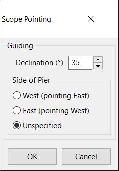
Place the telescope east or west of the pier, pointing south, with the declination shaft horizontal. Slide the counterweight on the RA shaft until the system is balanced. Many users intentionally set the balance slightly off to one side to keep any backlash loaded consistently.
Conclusion
Counterweights are not a relic of the past. When applied intelligently, they enhance comfort, reduce mechanical stress, and ensure smooth, precise operation for both visual observing and astrophotography.
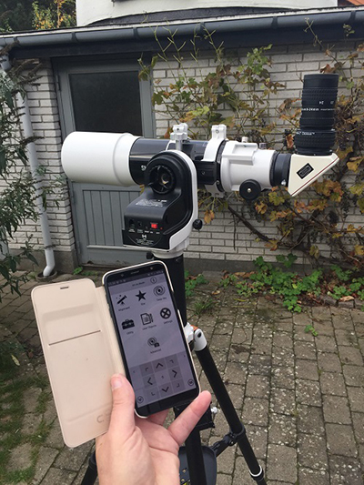
Make it even easier to align and operate your Panther Mount by using the SkySafari App. With the app, you can align the mount, control its movements, and access any object in the extensive catalog.
This solution seamlessly integrates with the mount’s handpad, allowing you to switch between using the app and the handpad as needed. The app excels at finding objects, while the handpad offers more precise control for fine adjustments. Using the handpad also helps preserve your night vision, as it lets you keep your eye on the eyepiece without the distraction of screen light.
Read on to learn how to make the most of this setup.
Equipment Needed
In addition to your TTS-160 Panther mount, you will need a NEXUS-II Wi-Fi adapter and a Phone or tablet with the SkySafari App installed.
(All Panther mounts are delivered with the NEXUS-II adapter included with the mount head).
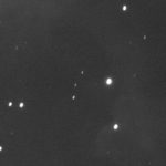
Decide on the first alignment star. Use SkySafari in “Augmented Reality” mode to help identify the star.
Slew manually to the star using either the mount handpad or the arrow keys in SkySafari, or make a goto from SkySafari (Note that the goto will not be very precise as the startup position is only loosely defined).
Center the star precisely in the eyepiece and click align in SkySafari. This sets alignment star 1, and the handpad screen will change to Align * 2.
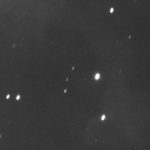
Repeat the process for alignment star 2.
Alignment is completed. Handpad will return to the standard operation screen.
Now the mount is aligned and you can make go-tos to any object in the SkySafari catalogues.
Camera rotators are today primarily used to frame the target when taking Astrophotos. With the newest high-resolution camera rotators, it is now possible to take perfectly tracked Astrophotos with an Alt-Az type telescope mount. Why bother doing that? Well, it means faster setup with no polar alignment and undisturbed imaging from east to west, with no meridian flip to worry about.
Read on and learn how it’s done…
Let’s start with a fast summary of how it works:
Step-by-step procedure for an imaging session with an Alt-Az mount with a camera rotator
Set up the mount and telescope. No levelling of the tripod is needed.
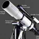
Install and connect the imaging gear as usual: Main camera, filter wheel, off-axis guider, guide camera, camera rotator, and motor focuser.
Power up everything, including the PC and the needed software apps.
Move indoors if desired and continue from a remote desktop. No need to be outside for Polar Alignment when it gets dark.
Perform a 2-star alignment using plate solve.
Slew to the target. The camera rotator will allow for precise framing as planned.
Start camera rotator tracking.
Perform the steps to take the sub-exposures. Either manually or via a predefined sequence:
Run autofocus.
Calibrate and start the autoguider.
Take the subs.
Continue all night – no Meridian flip to worry about – as part of a predefined sequence or move on to another target.
Want to know more – here follows the procedure with more details added
Step-by-step procedure for an imaging session with an Alt-Az mount with a camera rotator
With details included
Set up the mount and the telescope. No levelling of the tripod is needed.
Many Alt-Az mounts don’t require a levelled tripod, making setup easier and faster
Install and connect the imaging gear as usual: Mount, Main camera, filter wheel, off-axis guider, guide camera, camera rotator, and motor focuser.
If you are accustomed to long-exposure astrophotography, you are likely familiar with the necessary gear and its connections. Perhaps you even have everything installed and assembled on the OTA for quick setup without any cable hazards. There are two crucial things to be aware of:
Autoguiding must be done with an Off-axis guider (OAG). This is because the guide camera must rotate in tandem with the main imaging camera. It means the imaging train on the telescope must resemble this configuration:
Power up everything, including the PC and the necessary software apps.
Using a PC is recommended to allow for the use of any brand of hardware and software.
You can now move indoors if desired and continue from a remote desktop. There is no need to be outside to Polar Align when it gets dark and cold.
As there are no physical adjustments to be made on the mount, everything can be controlled remotely. It means you can set up any time (even during daylight) and just start it remotely from wherever you are.
Perform a 2-star alignment using plate solve.
Point the telescope in any direction not too high in the sky. Take a short exposure, plate solve the image and use the coordinates to align star 1. Go to another part of the sky, some 60-90 degrees away, and repeat the process to align star 2. Read more about this process here or watch this video.
Slew to the target. With the camera rotator, precise FOV framing in both angle and position is possible.
Object RA and DEC coordinates, along with the camera rotation angle, can be found in the control software. As an example, the Framing assistant in NINA looks like this:
Simply drag and rotate the image FOV to the desired position, and the goto and plate solve routine will do the rest. The very user-friendly PLAY software from Primalucelab can also make the slew to target, including rotation of FOV.
Start camera rotator tracking
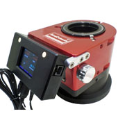
The tracking of the camera rotator is managed by the software provided by the manufacturer. In this case, I have used an Arco Rotator from Primalucelab.
Perform steps to take the sub-exposures, either manually or via a predefined sequence:
Run autofocus.
It is possible to focus manually or by using autofocus, both manageable remotely.
Calibrate and start the auto guider
I have used PHD2 for guiding. The procedure is the same as when guiding a Polar-aligned mount, except that the guide camera angles change as the camera rotator rotates. Therefore, the camera rotator must be connected to PHD2 to manage this, or the guider must be recalibrated at regular intervals. In my case, I’ve set up my NINA sequencer to do this hourly along with autofocusing, which has been working perfectly.
Read the article on Guiding the Panther Alt-Az mount with PHD2 to learn more about guiding Alt-Az mounts.
Take the subs.
Continue all night – no Meridian flip to worry about – as part of a predefined sequence, or move on to another target.
Some results:
I have used the system successfully for a few nights. I have used two different telescopes with the Arco Rotator from Primalucelab on the Panther Mount.
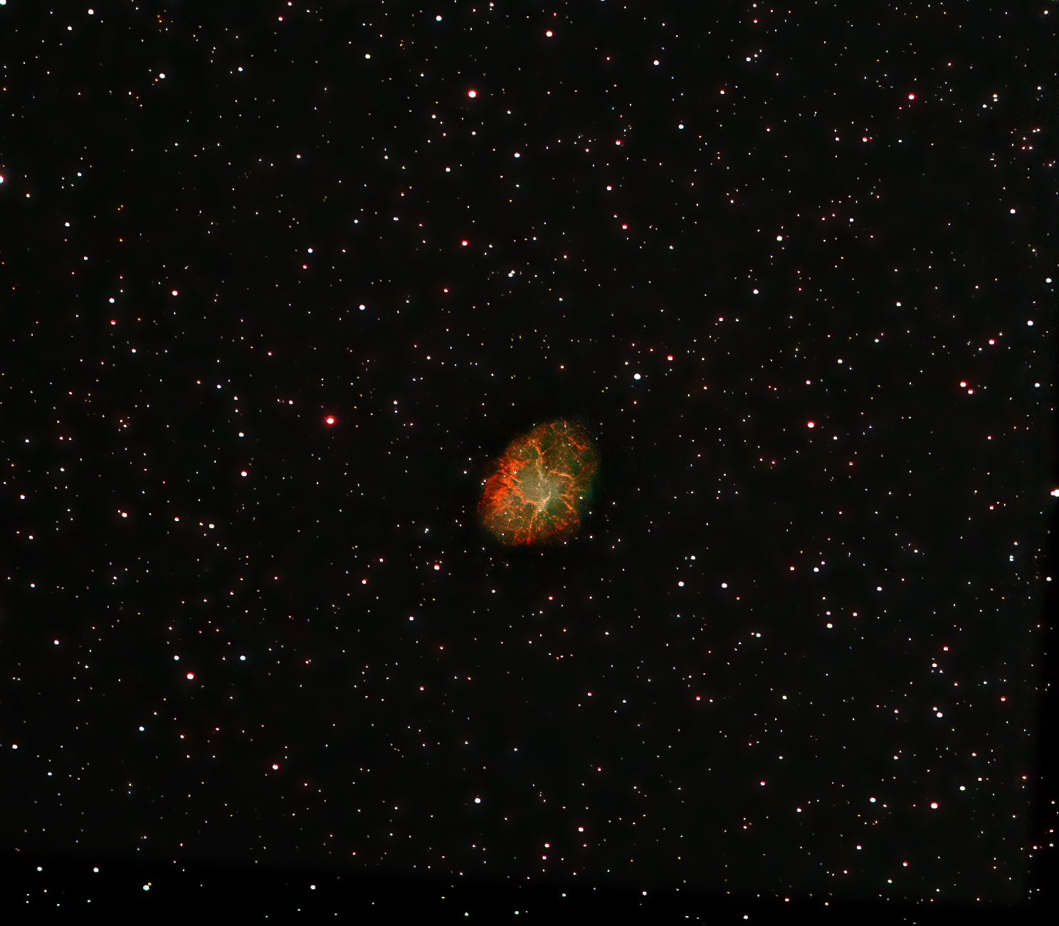
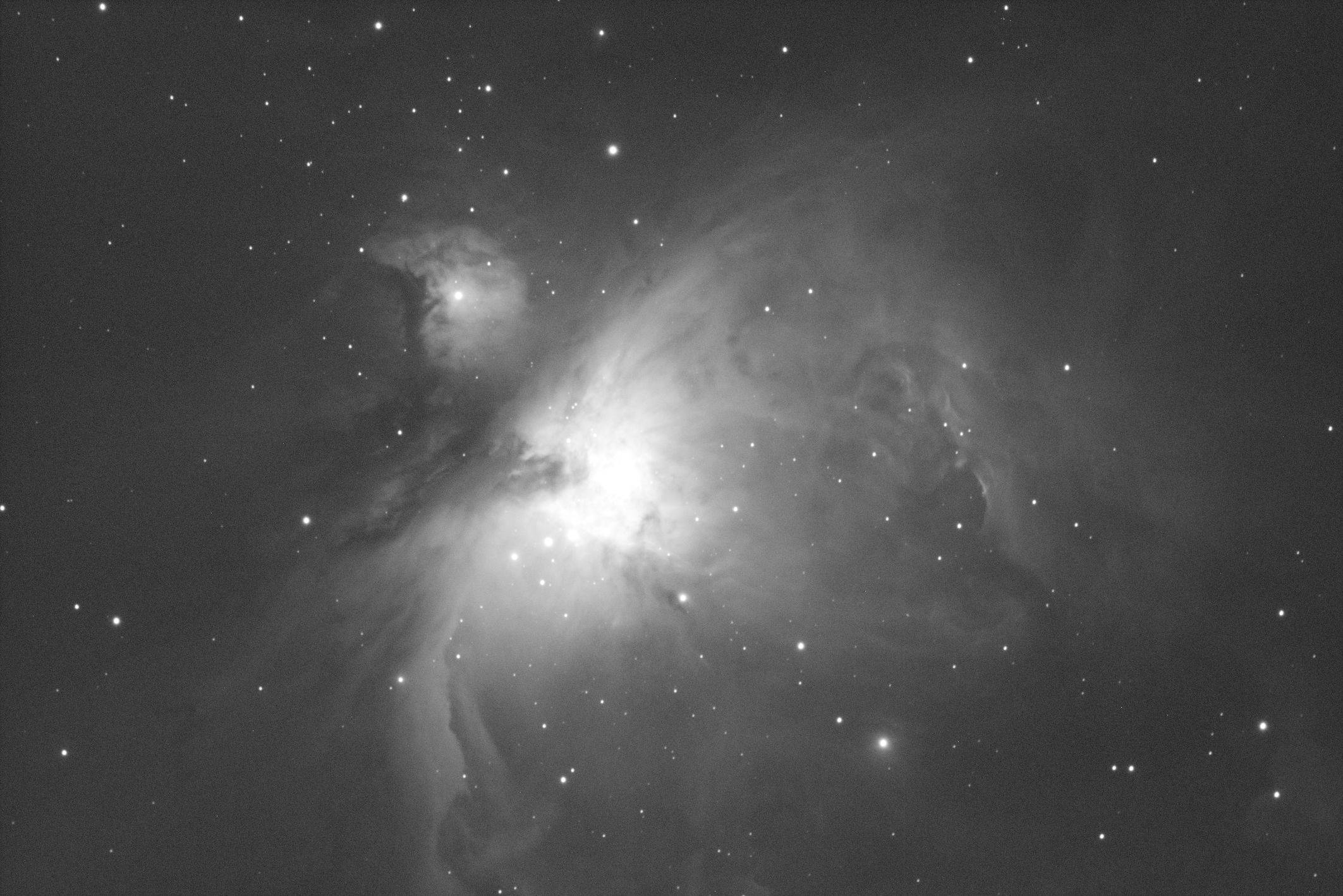
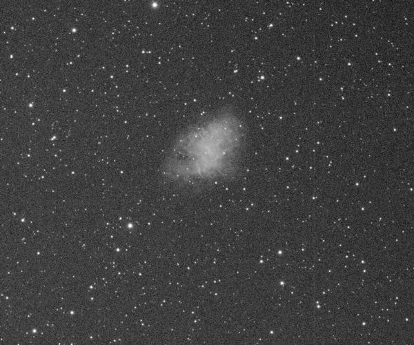
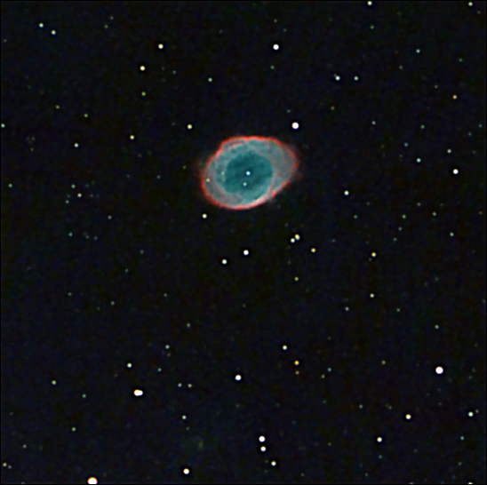
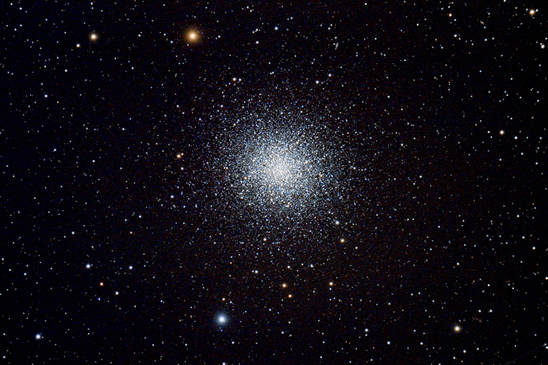
The first image is M27 imaged in One-shot-colour and HA.
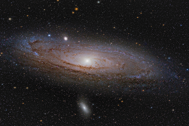
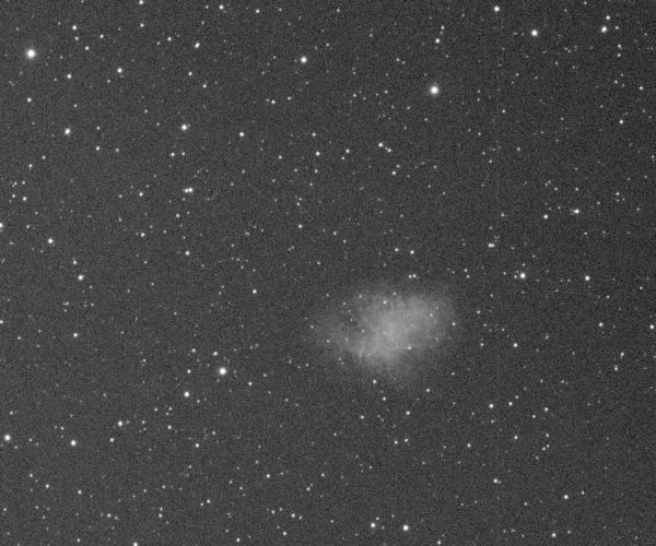
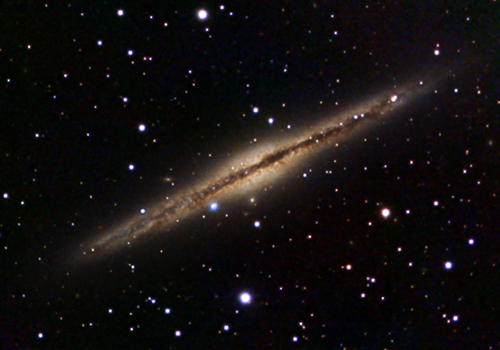
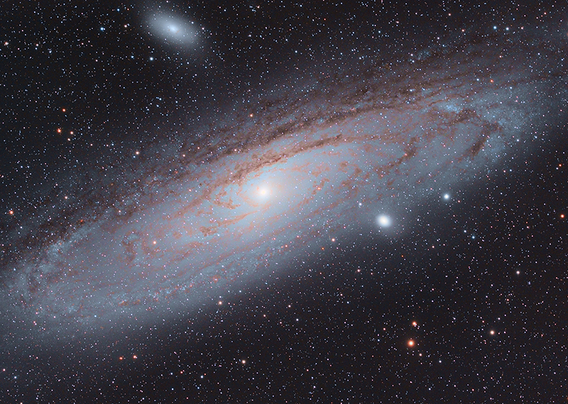
I also tried M33 with a longer combined exposure time. It took over two nights. The individual subs were 120sec, not to saturate the galaxy centre. All the images are taken in Luminance. Unfortunately, we are in a rainy period of the yea,r so there has been no chance to add colour data yet.
Demands for camera rotators for long exposure Astrophotography – ALT-AZ field de-rotation
Today, camera rotators are primarily used to frame targets when imaging with a polar-aligned setup. The demands for that operation are:
It must keep focus accurately when it rotates. It must not change the sensor position or tilt the sensor.
It must be able to rotate to a commanded angle and stay there. The angle resolution and the step size of the movement are not critical.
When the camera rotator is being used for alt-az field de-rotation, there are some extra demands:
The rotator must be able to track smoothly with very small step sizes.
The rotator must come with software that can control the de-rotation.
Let’s look at the extra demands for de-rotation use
How precise must the de-rotation be?
You might think adding the rotator will create new critical demands for the drive involved. But actually, the demands for the precision of the de-rotator are much smaller than expected!
When you guide your telescope mount there is a certain needed accuracy. This accuracy depends on the focal length, the camera pixel size and the seeing. In this example, we will focus only on the focal length.
If you imagi with a focal length of 1000 mm and the mount is guided with an accuracy of 0.4 arc-second, the error seen on the sensor at the focal plane will be:
So with a tracking accuracy of the mount head of 0.4 arc-second, the error on the sensor will be 1.9 µm.
When it comes to rotating the camera, the focal length has no influence. It is only the size of the sensor and the placement of the pick-up mirror for the Off-Axis Guider that matters:
This calculation shows that even with a full frame sensor the rotator must rotate 16 arc-seconds to move a star 1.9 µm at the OAG pick up mirror.
So the accuracy needed of the camera/telescope rotator is a factor of 40 less than what is needed of the main mount drives. Not so much to worry about!
Demands for the step size/resolution of the camera rotator
To get high-quality results, the camera rotator must have:
Step size smaller than 16″ equals more than 81.000 steps per revolution.
Note that these numbers are the same for any focal-length telescope.
The camera rotator was used in my setup.
I decided to use the Arco rotator from Primalucelab as it has a step size of only 1 arc second, making the movement very smooth. Together with the Sesto Senso focus motor, the system has worked extremely well. The PLAY control software manages the field de-rotation perfectly.
If you have any comments or questions, feel free to send me an email at nth@trackthestars.com
In this post I will explain how you easily can make a complete observation run remotely from a connected PC. As soon as the telescope is set up you can move inside and do the rest from the warm living room.
First lets look at:
The typical procedure starting up with a German Equatorial Mount
The mount, telescope and camera is set up – mount pointing north (or south if you are in the southern hemisphere) and levelled
Go inside and wait for darkness
Go outside and perform Polar alignment. This demands being out at the telescope using one of the polar alignment principles: polar finder scope, Polemaster camera or similar system, drift alignment etc. All demanding extra equipment and time.
Go inside and perform star alignment using camera and plate solve
The typical procedure starting up with a (Panther) Alt-Az mount
The mount, telescope and camera is set up (no leveling needed)
Go inside and wait for darkness
Perform star alignment using camera and plate solve
With the Alt-Az mount you don’t need to perform Polar alignment and you can stay inside as soon as the telescope is set up. Very nice especially in the cold seasons.
Let’s look in more details at how the remote alignment of the Panther Alt-Az mount is made:
STEP 1: Setup the mount and the telescope
Setup the Pier or Tripod – no levelling needed
Install mount head
Install the telescope with camera (to run it truly remote an electric focuser is needed)
If you want to do long exposure AP install a guide scope. If you want to do EAA no guide scope is needed
Connect mount, camera, focuser and guide camera to the PC
Power up the complete system with the telescope in horizontal position.
Slew the telescope to point in the direction the celestial pole. First slew to approximately north and then slew up in altitude. The altitude needed is the same as your latitude. IMPORTANT: Step 7 is only to help the plate solve so no accuracy is needed or has any influence on the precision of the final alignment. So just do this fast.
Now you can wait until it is dark. The next steps are all done from the PC. This can be outside at the telescope or from a remote desktop connection from indoors.
STEP 2: Perform a 2 star alignment from the PC (at the telescope or from inside using a remote connection to the PC at the telescope)
Perform a “blind” (meaning you just leave telescope where it is pointing) one star alignment on Polaris. This is just to tell the mount approximately where it is pointing to help the plate solve process.
Start your camera control app (Sharpcap, NINA, MAXIM, SGP …) and connect camera and mount.
Take a short exposure (1-5 sec) and make a plate solve. The plate solve gives the RA and DEC of the center of the FOV
In the TTS Handpad App use the solved RA, DEC coordinates (use JNOW) to align star #1
Use the handpad app to slew the telescope 30-50 degrees away in Az.
Take a short exposure (1-5 sec) and make a plate solve. The plate solve gives the RA and DEC of the center of the FOV
In the TTS Handpad App use the solved RA, DEC coordinates to align star #2
The mount is now aligned and you can start doing EAA or take AP.
I know there are opinions about what is the right way to do it, but for me the most important thing is that you do it and enjoy it:-)
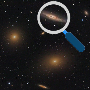
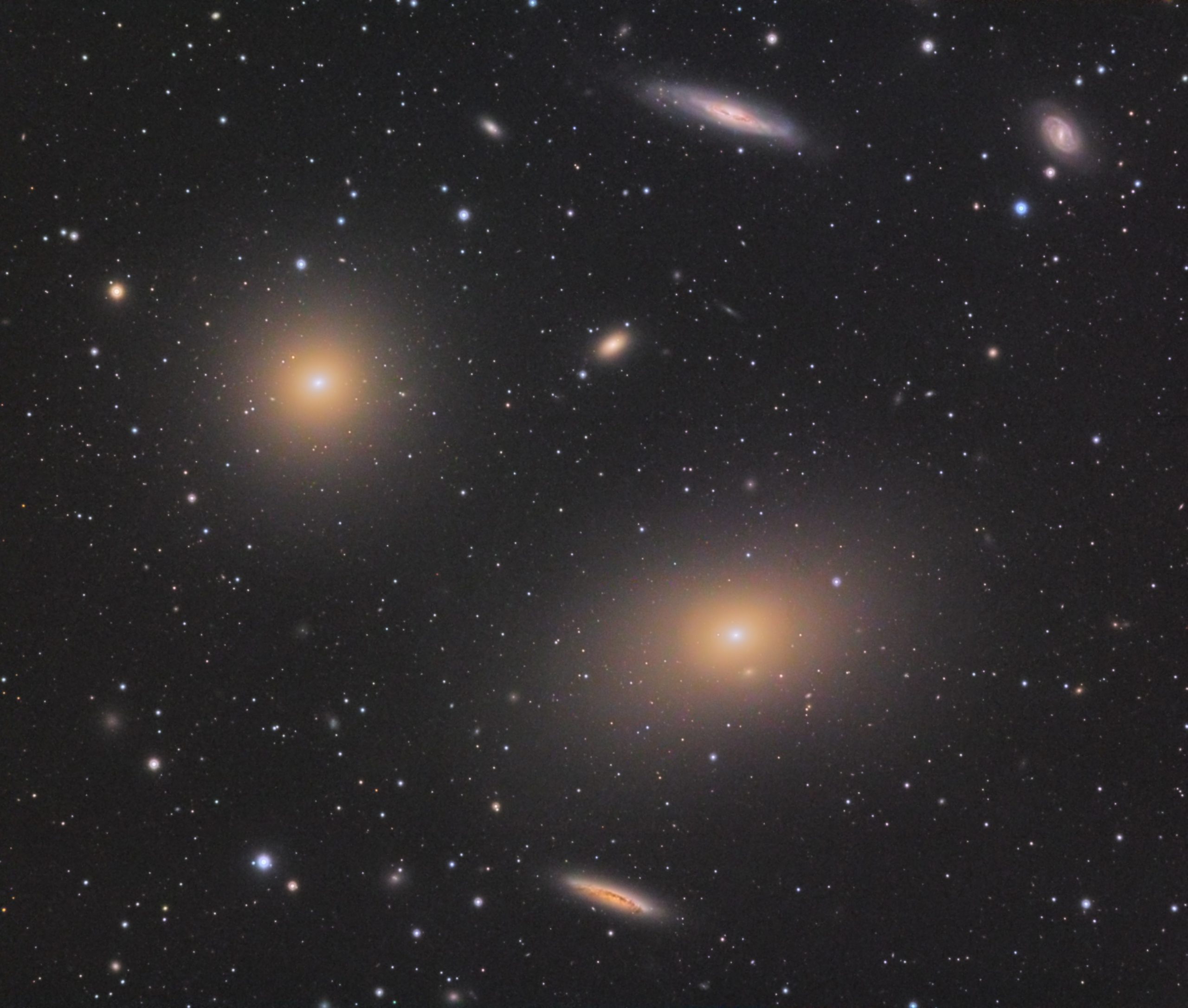
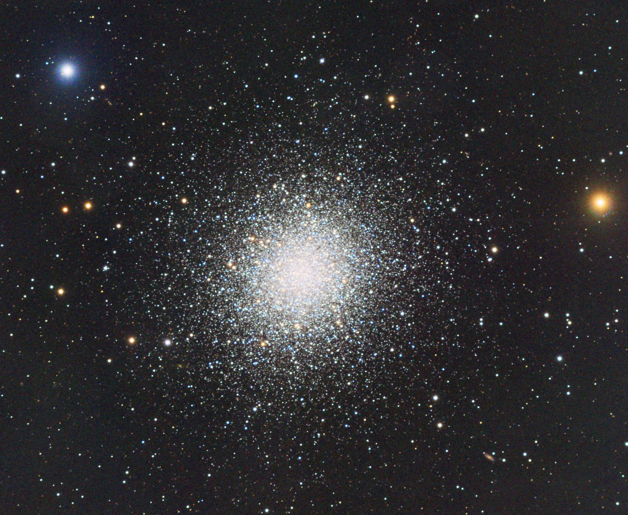
The Messier Catalog
There are 110 objects in the Messier Catalog – 40 Galaxies, 29 globular clusters, 27 open clusters, 6 diffuse nebulae and 4 planetary nebulae. In declination, they span from -34.8 ° to +69.6 °.
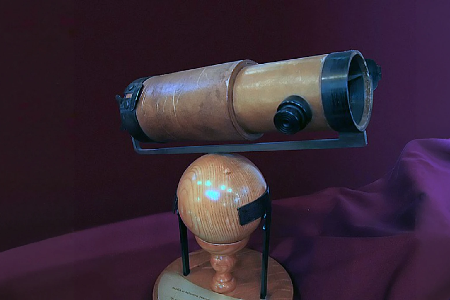
They were all discovered by Charles Messier from Paris about 250 years ago. He used a small refractor about 3.5″ in aperture to make his observations so all the objects can be observed with almost any modern astronomical telescope if you have the skills and a dark sky.
When can you make a Messier Marathon?
Over the year the sun position in the sky changes along the ecliptic. A big sky area around the sun is impossible to observe hiding objects in that direction. Funny enough there is a part of the sky where three are no Messier objects and that is around the spring equinox. In this all sky map the sun is at the edge (left or right) at declination 0.
Copyright: Wikimedia
So from late February to late March where the sun is in this area we have the possibility to perform a Messier Marathon.
Besides the sunlight it is also preferable to avoid too much moonlight. Therefore, the best time is aroundthe new moon in March.
The best time in 2023 is the week around the new moon from 18. March till 26. March
Can you make a Messier Marathon from where you live
The only thing to consider is the latitude you observe from. Charles Messier observed from Paris at a latitude 49o North. It means he was able to observe down to declination -41o placing the southernmost object in his catalog, M7 only 6o over the horizon when passing the meridian. If you live further south the southern objects will be easier to observe but the northern will be more difficult and vica versa.
To find the observable objects from a given latitude, it must be examined how high in the sky they will be in the evening and the morning twilight. That can be done using different tools. Here follows a table showing the number of objects you theoretically can observe at different latitudes on March 21.
The most important thing from this list is the sequence. When observing for the first objects shortly after sunset, it is important to take them in the right sequence to have the best chances for success. Besides this,s the list holds the most important object data and a check mark column to mark it as observed.
Planning the Messier Marathon – visual finder maps
You can use either electronic maps or maps on paper. But remember that looking at a screen always has an influence on the eyes’ dark adaptation. Maps on paper also need illumination to read, so perhaps the issue is the same. Do as you prefer and are used to.
Here is an example of a map from Freecharts.com. These maps are generated as PDF files and can be viewed or printed.
Planning the Messier Marathon – using goto
Most telescopes with GOTO capabilities will have an onboard catalog of the Messier objects. It is possible to use that combined with an object sequence list.
Another possibility is to connect a Phone/tablet or a PC to the mount and use a planetarium software to perform the gotos.
For the TTS-160 Panther mount, we have created a Messier Marathon object list that can be used from the handpad app. It holds the objects in the right sequence.
What telescopes can be used for visual observations?
For his observations Charles Messier used a 3.5″ refractor of mediocre quality compared to modern optics. Therefore almost any telescope with an aperture above 3″ can show all the messier objects from a dark location. But in the case of the Messier Marathon many of the objects must be observed at very low elevation and against a not completely dark sky. Therefore a larger aperture gives a much better chance of viewing all the objects.
Refractor 3-4″ Aperture is possible to use
Refractor 5-6″ Aperture is good to use
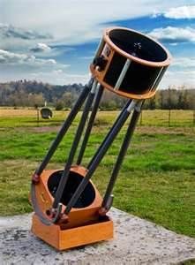
Reflector 8-12″ Aperture is very good to use.
I will not go into details about eyepieces, but try different magnifications if you can’t spot the object. A higher magnification can darken the sky background, increasing contrast.
A modern setup for doing an EAA Messier Marathon in 2023
The Messier objects are very easy targets for any telescope equipped with a modern Astro CMOS camera. So almost any telescope you might have can be used.
Actually it is more important to have a good mount to hold the telescope. There is only few minutes for each object so it is important that the mounting can perform a fairly precise gotos to frame the targets. Time used to recenter targets manually or via plate solve will be a problem. There is only about 5 minutes per object on average…
Here is a list of needed equipment:
A telescope
A Camera – A DSLR or a dedicated astro camera – preferably one-shot color.
A good mount – preferably an Alt-Az mount for easy alignment before darkness
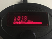
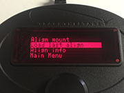
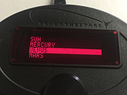
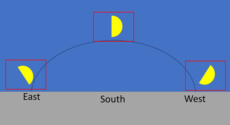
Alt-AZ mount: Use the sun and a few bright stars for early alignment
Polar aligned: Hurry to do the alignment when it is dark enough.
Focus the camera
Start looping exposures of the desired exposure time. 10-30 seconds might be a fair choice.
Now move the telescope to the target manually or using goto.
When you have seen the object on the monitor, move on to the next. Perhaps save the image for the records
The Automated way:
Create scripts/sequences for the software you use (NINA, SGP, Sharpcap). Group the objects into smaller scripts following the Messier Marathon sequence.
Run the scripts and watch the object appear on the screen
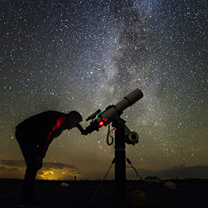
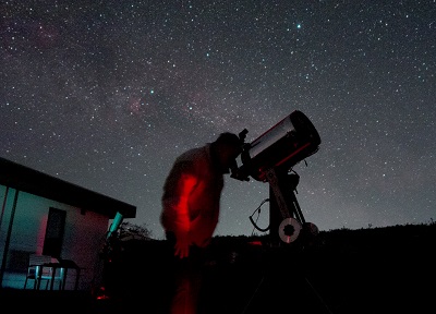
“The struggle of setting up all the telescope equipment often stops me from getting out to observe“
I am sure most of you can recognize this situation: The sky is wonderfully clear, and the coming night will be great for observations. But do I have the energy to pack all the gear, set it up, connect all the cables, computers, cameras, batteries, etc.? It can be quite a task when going into the backyard or travelling to a darker sky site. And if you are unlucky, some vital part is missing when you make the setup far from home.
A solution could be to build an observatory, solving all the setup hassle. But do you have the space in your backyard? What about light pollution? You could set up an observatory somewhere out of town, but that might be even more complicated.
One solution is to have a Mobile Observatory.
A mobile observatory will give you most of the same benefits as a fixed observatory and some extras too:
The complete setup with mount, telescope and all accessories can be permanently installed and ready to use
There will be room for a worktable with sky maps, a computer etc. you can even install larger screens on the walls.
You can install heating elements for those long cold nights.
You can have an integrated electrical system with good battery power and internet access.
You can go where you want: To real dark sky sites, to an occultation line, to see the ISS cross the moon – all the things that seldom happen just at your fixed observatory.
You can participate with all your gear at Star Parties or outreach events.
There are also a few things to consider with a mobile observatory:
How to avoid shaking the equipment too much when driving with the observatory
Good suspension on the trailer
Extra shock relief between the trailer and the equipment
How to avoid rocking the mount when moving around in the observatory or if it is windy.
The Telescope pier must not touch the observatory trailer when observing.
Select a telescope mount for the mobile observatory.
Space considerations
Typically the mobile observatory will have a limited size. It is, therefore, worthwhile to consider how much space the telescope mount will take up.
See this comparison between the footprint of a centrally placed Alt-Az mount and a German Equatorial Mount.
An Alt-Az mount will be much easier to get around in the observatory. Having guests over exemplifies the importance of conserving space in a small observatory.
Time used to get ready to observe – alignment time.
Most German Equatorial Mounts demand that you first use time and energy on levelling the pier, then making a polar alignment. This process will take some time out of your schedule and is certainly relevant to consider if you plan to use the observatory for short observation trips.
Alt-Az mounts do not need polar alignment, and many don’t need a levelled pier. For the TTS-160 Panther Mount, this also counts when you plan to do long-exposure astrophotography using the telescope rOTAtor.
So for Mobile Observatories, the obvious mount choice will be an Alt-Az Mount.
Takes up less room in the observatory
Faster and easier to start up with NO polar alignment or levelling needed.
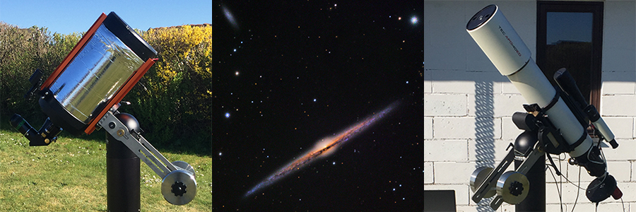
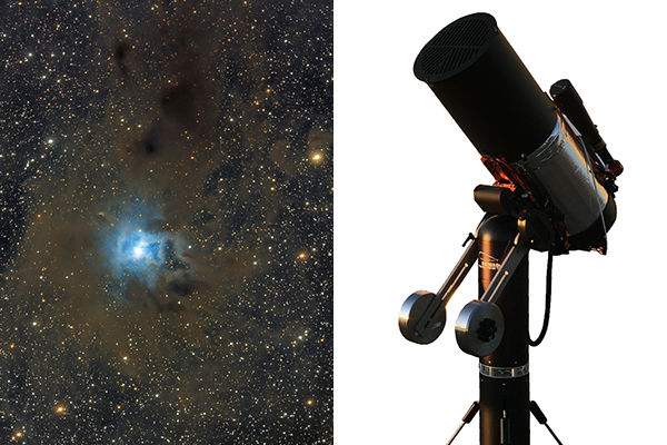
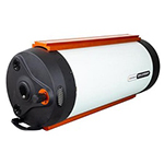
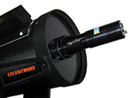
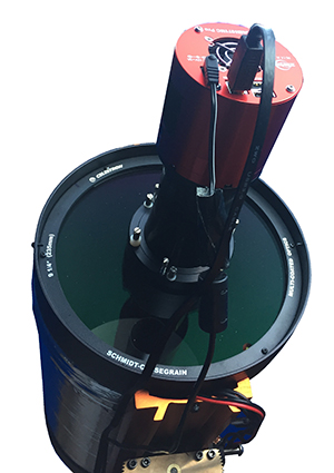
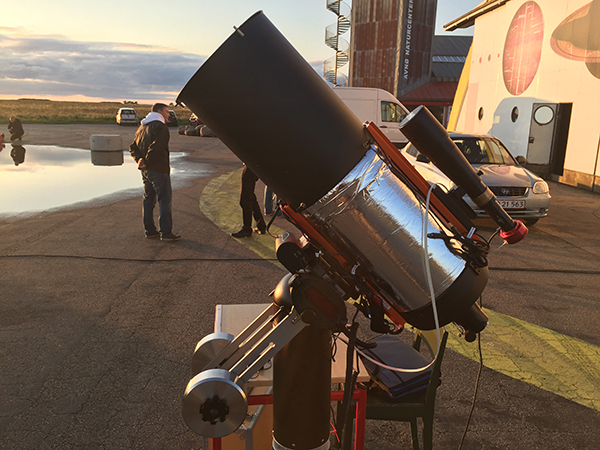
An example of a Mobile Observatory with 9.25″ and 11″ Celestron SCT on a Panther mount
Here I will show you an example of a Mobile Observatory set up by David Ryan of Indiana, USA.
Here is what Dave has written about the observatory.
The trailer and pier were manufactured by Pier-Tech in the U.S. in Bartlett, Illinois. This is a suburb of Chicago, about 40 miles northwest of downtown. The Pier-Tech pier raises and lowers while maintaining alignment allowing for easy access to the eyepiece. We also use a bigger version of this pier in our (Calumet Astronomical Society) main observatory. It allows people of different heights to reach the eyepiece comfortably including folks in wheelchairs and children.
The adjustable pier sits on a very heavy steel plate that in turn can be raised off of the trailer floor by hydraulically extendable legs. This allows one to walk around in the trailer and not cause any additional vibrations. Because I was constantly stepping on this plate accidentally, especially at night, I constructed a wooden platform around the plate that still allows it to rise but lets me get closer to the telescope.
The roof is motorized and can be fully retracted.
The observatory itself runs off of two batteries, one for the hydraulics and one for the roof and pier. There is then a battery used for the scope and accessories.
I added solar panels to maintain the charge in the batteries along with a chair, toolbox, retractable shelves, acacia floor tiles, analog clocks (they look cool and I feel you have to have clocks in an observatory!), solar cell controllers, and red/white LED lighting. I added a spare tire, the Panther mount , and I use several different scopes. I use a Celestron 120mm refractor with a Daystar H-a filter, which I also use on the C-11, a C-9.25 as well as a Meade 60mm Solarmax.
Using primarily a Mallincam, I can project live images to a screen mounted on the door. There is also another screen below it that I use to display simulations and information on what is being viewed.
The whole thing can be towed behind my SUV but the next project is to add a nose-cone to the front of the trailer. That big flat surface halves the gas mileage I get.
EAA (Electronic Assisted Astronomy) is Astrophotography kept simple – Alt-Az mounts are tracking mounts kept simple – A perfect match
I define EAA as taking short exposure astrophotos and displaying them live. Typically the setup is simple with a One Shot Colour Camera on a telescope carried by a tracking mount. Stacking on the fly of more short exposures is often used. This will make the image improve over time as more frames are added to the stack. When the image is as wished, it is time to move on to observe another target. It’s Live – It’s simple. And it is a great way to “Observe” faint objects and show them to the general audience when doing outreach.
The mounting for EAA – why Alt-Az is the simple choice.
EAA is much like visual observations. You want to use the time to observe and not fiddle with equipment. Everything should be as simple as possible.
Just make a simple two star alignment and you are ready
One important thing to be aware of is tracking accuracy. Even though exposures are kept short like 5-30 secs the tracking must be quite good. Many Alt-Az mounts are made mainly for visual observations where this kind of accuracy is not needed. So be sure to use a high quality mount if you want to get the best experience when doing EAA.
It is also possible to auto guide many Alt-Az mounts – Read how to here
Not needing to worry about meridian flip is another great thing from the Alt-Az design.
Field rotation – no issue for EAA
As you probably know the field of view rotates over time when tracking an object with an Alt-Az mount. This is no issue when doing EAA because the short exposures do not show the field rotation. When stacking multiple frames the stacking software automatically aligns the individual frames eliminating any rotation.
Telescopes and cameras for EAA
Any telescope can be used for EAA. As with all other types of observations a larger aperture and good quality optics will be an advantage. We are not aiming at getting an APOD (Astronomy Picture Of the Day) but rather to observe an object live, with more details than what is possible visually. For most targets, a low f-number (eg 3-5) will be best but even at f/10 many great observations can be made.
As I expect you are already a visual observer I think getting a good visual telescope and using it for EAA is generally the best way to go.
Most observers prefer a colour image so a One Shot Colour camera is the obvious choice. The market is full of CMOS Astro cameras and they can all be used for EAA. If you believe this is something for you I suggest a cooled camera but an uncooled camera does a very good job with the many short exposures.
If you observe from very a very light-polluted area it is a possibility to use a monochrome camera and narrow-band filters.
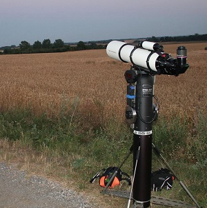
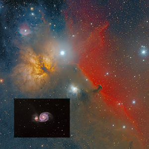
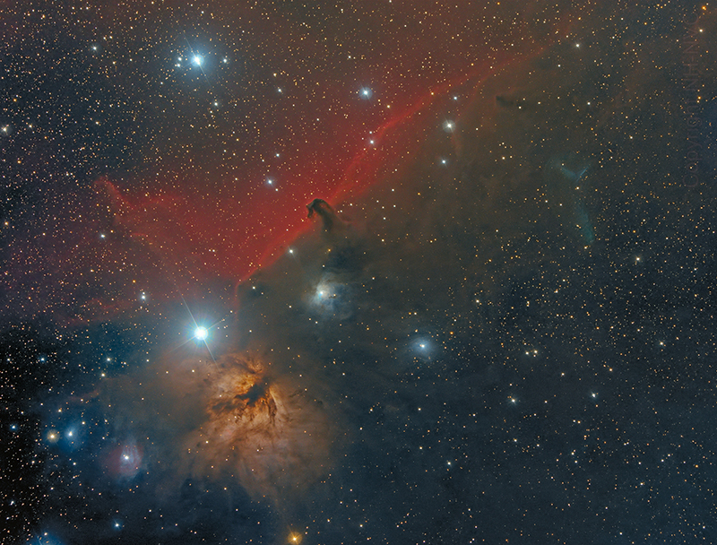
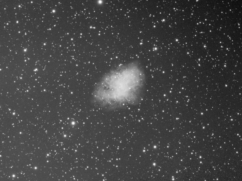
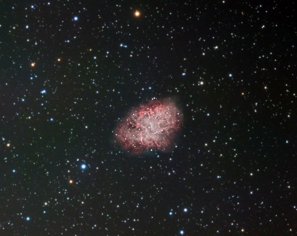
This is an Astrophoto but could be an EAA live image as well. It is numerous 30 sec unguided exposures taken with a Canon DSLR through a TEC140 telescope sitting on a TTS-160 Panther mount.
How to do EAA with the Panther Telescope mount
– outside at the telescope or remotely from indoors on a cold winter night
The Panther Alt-Az mount is extremely well suited for doing EAA. The simple setup and fast start-up combined with good tracking accuracy make it easy and nice to use. If you should want to take deeper astrophotos it is easy to add auto-guiding and field derotation. This article will focus on EAA.
EAA STEP-BY-STEP GUIDE
1. Set up the mount and telescope
You can quickly set up the mount with no need to level the pier and no need to Polar Align. Install the telescope and camera and set the balance.
First, connect the camera to the PC. Typically, a one-shot colour camera just needs a USB cable to the PC. Many cameras are powered through the USB connection, but some will need separate power.
The mount connections are made based on how you would like to control it:
Using the handpad at the telescope
If you just want to use the handpad, you don’t need any connections between the mount and the PC. Just plug in the handpad and the power.
Use the handpad together with a planetarium application on the PC (aligning at the telescope, EAA observations from indoors if wished)
In this case, you will use the handpad for the basic alignment and then afterward use a PC application for slewing to the targets (over Ascom). You must plug in the handpad, the power cable, and an Ascom cable from a USB port to the PC port on the mount head.
Use the PC for all controls (aligning and EAA observations from indoors if wished)
To have complete control of the mount from the PC you must plug in the Handpad to USB cable and use the remote Handpad Emulation App to control the mount. Besides this, you can also connect an Ascom cable to control the mount from any PC application using Ascom.
3. Aligning the mount
Aligning the mount manually at the telescope
The easy traditional way is just to make a two-star alignment with an eyepiece in the telescope. To get the best tracking be sure to center the alignment stars precisely. You can also install the camera and use that for the alignment. If you use live video it is very easy to find and center the alignment stars.
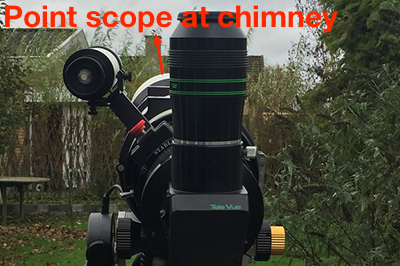
If you have cold winter nights, like we often have in Denmark, you might want to get indoors as soon as possible. When you have set up the complete system, point the telescope in the direction of the pole star. No need to point precisely. It does not even need to be in the finder scope. You can do it in the daytime, just knowing approximately where north is and the approximate altitude (the same as your latitude).
Now at the PC – indoors using a remote desktop or outside at the connected PC:
Connect the “Handpad Emulation app” to the mount
Using the Handpad app, make a One-star alignment on Polaris (This will set the mount coordinates near where the telescope is pointing. It is ok if it is off by several degrees)
Get the camera running and focused.
Connect the plate solve app to the mount using Ascom. (This will feed the mount pointing coordinates back to the plate solver, giving much faster solves and fewer failures)
Take a short exposure (1 sec). Plate solve the image. Notice resulting RA, DEC.
Use the handpad app to make a One-star alignment and use the plate solve coordinates (RA, DEC) as alignment target (Menu path: Align Mount – 1 star – Coordinates). The mount is now tracking. (For the most precise alignment, repeat steps 3 and 4 now with the mount tracking.)
Using the handpad slew the telescope in Azimuth some 60-90 degrees (distance not important)
Take a short exposure (1 sec). Plate solve the image. Notice resulting RA, DEC.
Use the handpad app to add a 2. alignment “star” and use the plate solve coordinates (RA, DEC) as alignment target (Menu path: Align Mount – 1 star – Coordinates).
The mount is now precisely aligned, and the alignment takes the unlevelled setup angles into account.
4. Slew to the targets and start observing
With the mount now aligned, it is easy to slew to any target using the Handpad or the Handpad App and any connected Planetarium software.
Set the handpad to Display Field rotation coordinates. The left coordinates will then show the maximum number of seconds it is possible to expose one sub without getting visible field rotation. This can be a great help in picking the best exposure time.
Sometimes it seems like everybody has thrown out their eyepieces and only images the sky. Even though Astrophotography is hot there are many astronomers who wants to SEE the objects live with their own eyes. Some even acquire sets of eyepieces to be able to enjoy the wonders of the sky with both eyes…
In this post I will look a bit into the subject of Bino viewing. By Bino Viewing, I mean any solution where the observer uses both eyes when observing
Binoculars
Bino-viewers – Beam splitting device installed on a single telescope
Bino-Scopes – Two identical telescopes installed in parallel
The post will touch the following subjects:
The advantages of observing with two eyes
The bino-viewer
The bino-scope
Telescope Mounts for Bino Viewing
The advantage of observing with two eyes
Relaxing and easier to see small details Observing with two eyes means that both eyes receive the telescopic view of the object. This is how our eyes are meant to be used, so it will for most observers feel more relaxed and natural. Small details hardly visible will be easier discerned by the brain, when the same signal is coming from both eyes. So using both eyes gives a more comfortable observing experience and allows for seeing smaller details.
A 3D experience
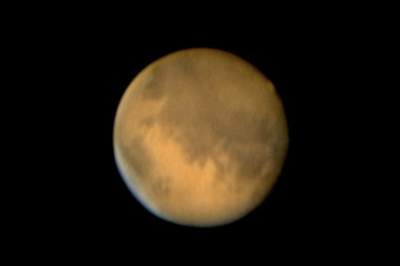
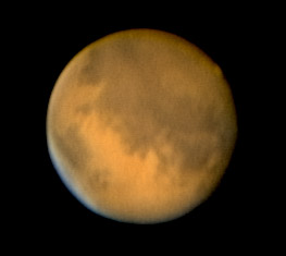
Real 3D views that you can get on terrestrial objects are not possible due to the distance of the celestial objects. But it is often reported that a 3D effect can be seen when observing with both eyes. Especially on the moon and the planets.
Observing faint objects When it comes to seeing faint objects, two eyes will also do better than one eye if the light intensity is the same. If you add a beam splitter to a telescope, so that each eye only receives 50% of light, it will be more difficult to see a faint object than if you use one eyepiece on the telescope and get 100% of the light into one eye. But the difference might not be so big as it sounds.
It comes at a cost Observing with both eyes means you will need extra equipment and two of each eyepiece you use.
Let’s look at the needed equipment.
The bino-viewer
A Bino-viewer is a unit you install in the telescope focuser that splits the light into two eyepieces. Generally speaking a bino-viewer consist of:
A beam splitter
Sets of prisms or mirrors to direct the light to the two eyepieces.
Two eyepiece holders with adjustable distance to match the observers eye distance.
Sometimes a barlow lens can be installed in the front to help get the device in focus.
This basic principle can be twisted to make many different versions of Bino-Viewers. I will not go into details with this but just point out that the quality of the Bino-Viewer is very important. It contains several optical elements that must be of excellent quality and correctly aligned not to deteriorate the image coming from the main telescope.
Adding a Bino Viewer to an observation kit can be costly and it is necessary to get sets of identical eyepieces so the eyepiece budget doubles.
It is expensive to get two nice refractors but – as an example two TEC-140 APO will cost approximately 15.000 usd. To get the same combined aperture from a single telescope you will need a TEC-200 APO costing approximately 30.000 usd. So from a light intensity point of view the Bino-Scope solution is much cheaper – but of course the resolution will still be like a 140mm.
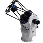
For larger aperture, reflectors is also a possibility:
16″ Newtonian Bino-Scope (Tom Dey)
A large Bino-reflector can be a bit difficult to handle with collimation and alignment of the two OTA’s but the visual experience on Deep Sky Objects is out of this world.
Telescope Mounts for Bino Viewing
Binoculars
For normal Binoculars and small Bino-scopes a completely manual mount can be enough and satisfying. Normal photo tripod style mounts can be used, but when you observe very high in the sky you will benefit from a special type made for astronomy.
Standard Photo Tripod & Astro parallelogram mount
Larger telescopes and Bino-Scopes
When the equipment gets bigger a better mount is needed. When selecting the mount there are some parameters to focus on.
Eyepiece position
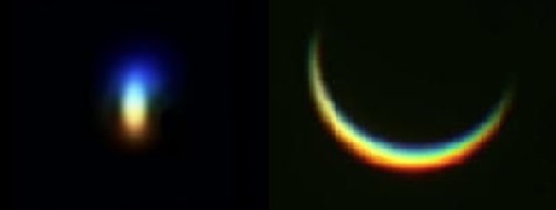
One very important thing to focus on is the eyepieces position. Getting both eyes in a good and relaxed position in front of the eyepieces is extremely important. If the mount tilts the telescope sidewards – like all polar aligned mounts do – you will end up having the head in unpleasant angles.
No Meridian Flip – a meridian flip will turn everything up-down making it impossible to use with a Bino-Scope
Alt-Az mount tracking pattern
Tracking and goto
When you observe with higher magnification tracking is a must. Goto is also great even if you sometimes prefer to star-hop to the targets manually. This points to a Motorized Alt-az mount. For single telescopes with Bino-Viewer a side mounted solution is possible. For real Bino-Scopes a top-mounted solution is the best.
Setting up a heavy Bino-scope
A large aperture Bino-Scope is both bulky and heavy. Therefore it is extremely important to consider how to handle the telescope when transporting and setting up.
A telescope mount with a top-mounted horizontal dovetail saddle is a great help when installing the telescope. It is possible to lift the telescope up on the saddle and rest it there while locking the saddle clamps.
To avoid lifting the telescope up too high, a Tripod with a geared column can be an advantage.Lower the Column completely – install the telescope – raise until the wished observation height.
Keep warm indoor, sleep all night – the automated system will collect light all night long.
Automating your astro-imaging is getting easier and easier all the time. New hardware and software solutions becomes available for the dedicated amateur astronomer. In this post I will tell how I have used the software NINA – Nighttime Imaging ‘N’ Astronomy to automate my imaging setup.
With the automated setup I am now able to start up all the equipment in 5 minutes. Then I select and start a premade session for the night. That’s it. Back inside waiting for the subs to show up.
Here is what the session script does:
Slew telescope to target
Recenter and rotates FOV to requested position based on plate solve.
Perform autofocus
Calibrates and starts the autoguider
Select filter
Takes the requested subs.
Slews to the next target – this also rewinds the Telescope rOTAtor.
I hope you will enjoy reading this and that it can help you setting up your own system.
First a quick appetizer on how simple it works
In the framing assistant in NINA I select target M33 – The Triangulum Galaxy. To get all of the Galaxy in the Field of view I pick a 2×2 panel mosaic and rotates the FOV as wished.
This targeting is automatically transferred into a Sequence with 4 targets – one for each panel.
I then input the number of subs for each panel. I keep the total exposure time per panel below 1 hours to stay within the Telescope rOTAtor’s tracking time.
That’s it. Just hit play and the subs are taken. To get longer total exposure time just run the sequence several time – the same night or over several nights.
Here is the resulting stacked frames showed in PixInsigt (not yet assembled to one image)
Getting all these frames on the harddisk was so easy. Processing it all into one color image that something else that I haven’t completed yet….
To enjoy this kind of automation you need to use some time to setup the system. Here is how it is done.
And a lot of cables, dew heaters etc. but I will leave that out (feel free to ask for any details).
I connected all USB cables from the different devises to the USB hub, that was installed on the counterweight arm (handpad magnet). So only one USB cable goes from the moving mount to the laptop.
The devices needing 12V power get that from one source again having only one power cable going onto the moving rig.
Setting up NINA and PHD2
You must have ASCOM, NINA and PHD2 on the computer to make an automated setup. All three software packages are free to download. Besides this you need a Plate Solve app. I use ASTAP.
In this paragraph I will focus on the settings needed for this type of setup and with extra focus on the settings when using Alt-Az mounts. For more general introduction to NINA and PHD2 check out the many tutorials available.
Note that for this setup NINA version 1.10 HF3 was used.
ASCOM
Download and install the latest version of the ASCOM Platform.
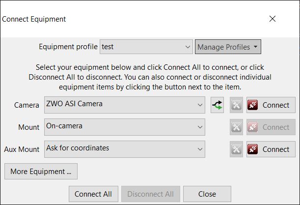
As mount select Device Hub Telescope. Using the Device Hub allows more software programs to communicate with the mount simultaneously. In this case NINA and PHD2.
To setup the Device Hub click on the settings icon .
This will start the Device Hub program.
Click Choose to select the Ascom driver.
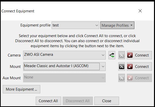
Select the correct Ascom driver. For the Panther Mount use Meade Classic and Autostar 1.
Click Properties to setup.
Select the relevant Serial Port.
Note on serial ports: Windows assigns the COM port number. Depending on the USB devices connected to the different USB ports this number can change. I suggest you always inserts the same Equipment into the same USB ports and connect everything before powering up the PC. This will ensure the different devices gets assigned the same way every time. Otherwise this can be cumbersome.
If you have problems finding the correct COM port number check the windows device manager.
Close the windows related to the Device Hub.
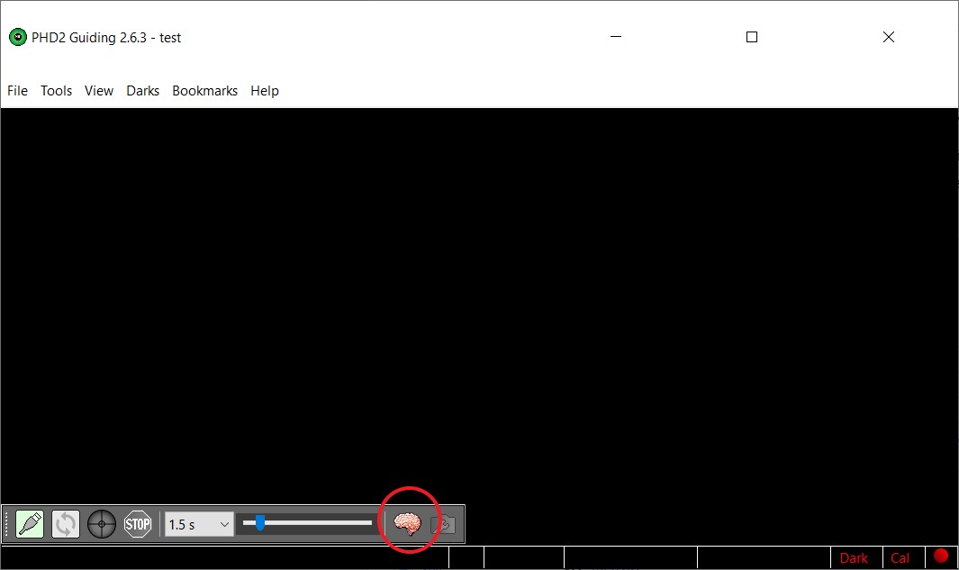
Finally in PHD2 you have to enable the Server.
Open the Tools menu and click on Enable Server.
This will allow for NINA to control PHD2.
This completes the setup of PHD2 in relation to the control from NINA. You still need to setup all the guiding parameters in PHD2 to get the correct guiding. If you have not done this before I strongly suggest that you do this before moving on to setting up NINA. There are many settings working together when everything is ready for automation. To know that PHD2 is working correctly together with the mount before moving on makes it easier to identify any problems occurring.
Related to the PHD2 setup I suggest you read my post: Guiding the Panther Alt-Az mount with PHD2
NINA Setup
Here I will take you through the settings needed for complete automation with NINA. After setting up it is necessary to test the system in small steps before running a complete automated session.
We will start with Equipment setup. On the Equipment setup tab we must look at, Camera, Filterwheel, Focuser, Rotator, Telescope & Guider.
Camera setup
Select the driver for your camera and adjust settings as needed.
Press Connect.
When the camera is connected you will get information about the camera and can control cooling etc.
Check that you can control cooling.
Filterwheel setup
(if you don’t use a filter wheel just move on to Focuser)
Select the driver for your filterwheel and adjust settings as needed.
Press Connect.
Try to change filter (watch/listen to know it is moving)
Focuser setup
(if you don’t use an electronic focuser just move on to Rotator)
Select the driver for your focuser and adjust settings as needed.
Press Connect.
Try to move the focuser by pressing the arrows and watch the focuser move.
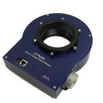
Rotator setup (this is the camera rotator)
The camera rotator is used to frame the targets to the wished FOV angle and to keep this angle after the automatic rewinding of the telescope rOTAtor.
In this case I have used a Falcon rotator but other brands can be used too.
First you must install the Falcon rotator desktop app that can be downloaded from Pegasus Astro website.
Select the Falcon Rotator driver.
Press Connect.
This will start the Falcon Rotator app but will NOT connect to NINA. You must press Connect once more and then the rotator will be connected.
You can test the Rotator by typing in a target position and press Move Mechanic and watch the movement.
NOTE: To have the Plate solve function working correctly with the Rotator the “Reverse” function must be off. This reverse functionality can also be setup on the Falcon Desktop app so keep an eye on this.
Telescope mount setup
Select the Device Hub in the drop down menu.
The setup of the Device Hub was already done inside PHD2 earlier (see above).
Press Connect
If you are asked to synchronize time and geographical coordinates say No.
When the mount is connected you will see the RA and DEC coordinates displayed. These will match the coordinates on the handpad.
The manual control buttons are not implemented in the Meade Ascom driver and will not work. If needed there are similar buttons on the Device Hub that works.
Guider setup
Select PHD2 and press Connect
If PHD2 is not started already the program will start up and connect to guide camera and Device Hub (mount).
When started and ready NINA will show a checkmark next to Connected.
This completes the setting up of the different devises connected to your system.
NINA Options
Next step is to look at the Options setup in NINA.
Under the Options Screen you find five Tabs. Here we will look at:
General
Equipment
Imaging
Plate solving
Again focus will be on the settings related to the automated use with an Alt-Az Mount. There are more settings that you can examine but what we cover here should do for a start.
On the General tab you must create a Profile for the system you are setting up. IMPORTANT: The Profile will be saved and can be loaded next time you start up with all settings ready to go.
Options – Equipment Tab
The camera section is automatic populated with basic camera data when the camera is connected.
In the Telescope section fill in the data as shown in the screenshot. Be sure to have the correct focal length as this will be used for plate solving. Set the settle time after slew to 20 sec to allow the rOTAtor to complete rewinding.
The setup of the Focuser section depends on your focus motor and the optical configuration. I suggest you find another tutorial explaining this.
The Filterwheel section must be setup. Focus offset is used if it is enabled in the focuser section. Auto focus exposure time is something to experiment with. I use 2 secs for LUM and RGB. For H-alpha I have tried with longer exposure time but generally autofocus in HA is difficult.
The Guider section can as a start be setup as shown in the screenshot. Depending on your guide setup some adjustment might be needed.
Options – Imaging Tab
In the left half of this tab you select the file format the images will be saved in and you can setup a file naming pattern allowing to include different image data in the file name.
The Auto Meridan Flip section is very important when you use an Alt-Az mount. The Auto Meridian Flip function must be disabled.
The Image Options section can influence how well the Plate solver works so especially the Star Sensitivity and Noise reduction must be watched. I like to have Annotate Image enabled so the HFR value can be displayed directly on the image.
In the Sequence section you set the folder for saving sequence files and you can decide what happens when the sequence is completed.
Options – Plate Solving Tab
I use ASTAP as the main Plate Solver.
You must download and install ASTAP before setting up in NINA. You will find all the needed information here.
Select ASTAP as Plate Solver.
In the Plate Solver Settings section input the path for the ASTAP .exe file. A search radius of 30 degrees is the default value and works fine. Downsample factor of 2 is also fine.
I use Astrometry.net as blind Solver. You need to register an account (free) at the website to get the API Key to input.
This completes the setup. It might looks overwhelming but you only need to do it once.
Testing the system in the Image Panel
The image panel is where you can control the equipment manually and where the images are displayed. I strongly suggest you test the individual parts of the setup on the Image Panel before starting an automated sequence.
Test Camera
Start the camera looping short exposures and see that the frames look correct.
Test Focuser
Push the arrows and watch the focus motor move.
Focus the image as good as you can using the arrows.
Test Autofocus
After having achieved a fairly good focus manually (important) try to start autofocus.
You should see the system create a V-Curve and find focus. This will take several minutes going through the steps.
There are several settings to play with to get the best results.
Test Plate solve
Now the camera is well focused. Take a short – like 5 sec exposure. Press the Plate solve icon and get the result. If you are using a wide field system ASTAP should solve every time in a few seconds. If you work with a small FOV it can be more difficult in parts of the sky with few stars.
Be sure it works fairly consistently before using it as part of a sequence.
Test camera rotator
Try typing a target position and watch the camera rotator move to the target position.
Now everything is ready for everyday use.
Setting up and running a sequence
A sequence can be setup either when you are ready with the telescope or you can do it beforehand so everything is ready when the sky clears.
It is possible to use the framing assistant as shown in the beginning of this post or you can can go directly to the Sequence Tab.
In the sequence tab fill in the following data
Target – Type in a target name/number. RA and DEC are loaded from the catalogue. Input a wished rotation angle (camera rotator angle)
Start Guiding – Switch on to start PHD2 guiding
Slew to target – Switch on to have the mount slew to the target
Center target – Switch on to have NINA precisely center the target based on Plate solving.
Autofocus – under the Autofocus section you can setup when an Autofocus must be made
Finally input details about the sub exposures you want the system to take.
PRESS PLAY
The system will execute the sequence as. While the sequence is running you can change to the image tab to view the images coming in.
Extended exposure time with the telescope rOTAtor using more targets.
When using the TTS-160 telescope rOTAtor you must watch it’s de-rotation time. On most occasion it will de-rotate at least 1 hour. Therefore when you set up the sub exposures keep the combined exposure time under one hour. To have more exposure time create a new target with the same target coordinates and angles. Be sure to enable Slew to target and Center target. Then add the subs for the next hour. Repeat as many time as wished.
When a new target is started the Slew to target command will automatically rewind the telescope rOTAtor and the Center target command will recenter the FOV both in RA-DEC position and rotation angle. So all frames will be aligned identically.
Conclusion
Getting all the it settings right for an automated system takes time but the spent time will come back many times if you like taking many long exposure astrophotos.
It’s getting easier and easier to use Alt-Az mounts for Astrophotography (AP). You don’t have to bother with levelling and polar alignment, so you can setup very fast and easily. With the many new computer devices it is also possible to control the system remotely. Most Alt-Az mounts can be used for short exposure AP as they are. When you want to take longer exposures you need a field de-rotator.
In this article I will explain how you can use the ASIAIR Pro computer unit to automate the imaging process. Most things are general for any mount type but I will focus on the things that needs special attention when using an Alt-Az mount.
This PART 3 article will focus on how you use the PLAN MODE for unattended imaging.
I hope you find the article interesting. If you have any comments or improvement send me an email at nth@trackthestars.com.
Planning an automated imaging session
To have success with unattended imaging good planning is important. Below is a number of things to consider related to the mount and tracking. In this article I do not look into cameras, filters, Field of view and other aspects that are just as important when you pick your targets.
The considerations related to Alt-Az mounts are:
Where in the sky is the target placed:
Plan to image when the object is highest in the sky around the meridian. There is no meridian flip to worry about.
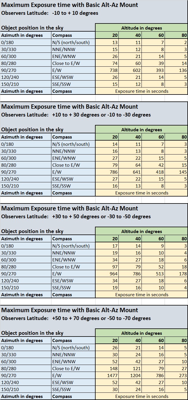
Avoid targets above altitude 85 degrees. That’s about the maximum altitude where an Alt-Az mount can track well. If the target gets closer to zenith than this shoot another target until the “dead zone” has been crossed.
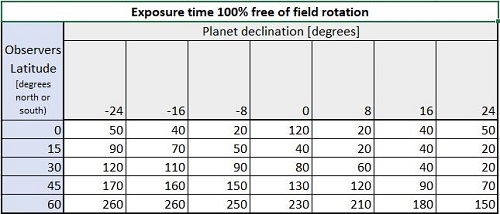
If you image without a field de-rotator it can be an advantage to image in East and West where the field rotation is slowest and allow for the longest subs.
Find a suitable exposure time for the individual subs
For a basic Alt-Az mount the field rotation sets the limit for the exposure time. Typically around 30 secs can be used for many targets. In East and West 2-3 minutes is possible. Have a look at this article to learn more about exposure time for the individual subs.
Here is an example on how I will prepare for tonight’s imaging session. We are in October and I am at latitude +56°. I plan to start imaging at around 20.00 local time . That will give me time to setup and prepare things.
I use different planning tools but Telescopius is a good place to start.
I have selected three objects:
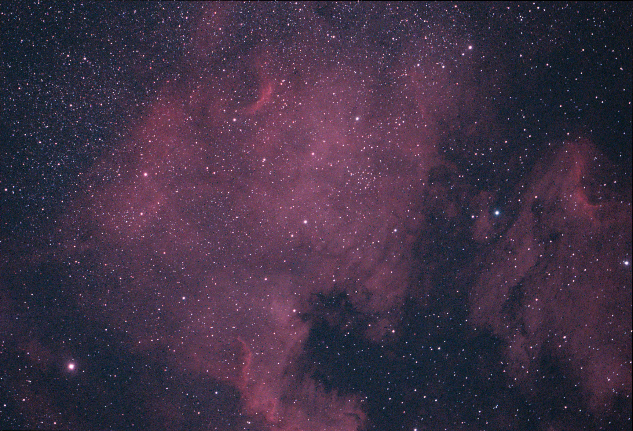
NGC7000 North America Nebula: Start 20:00 (Az: 190, alt: 78°), End 22:00 (Az:255°, alt: 66°) (max alt: 78°)
Based on the sky position the longest recommend subs will be around 20 secs without a field de-rotator (see table in this article)
With a field de-rotator the subs exposure time can be as long as wished
Now the plan can be typed into the AAP. You can do this indoor but must connect camera and filter wheel to the AAP.
Select PLAN MODE and open the settings
Open the list of PLANs to add a new plan
Select Add to create a new plan
Fill in the fields
Name your plan
Switch on Start Guiding if you have an autoguider connected (recommended).
Switch off Auto Meridian Flip. Never used on an Alt-Az mount
Set the starting time. This can be a certain time or it can be set to be started manually.
Set plan to end when it is completed.
Set the End Options as wished.
By shutting down the AAP you can also switch off equipment being powered through the AAP. I use this to switch off mount, dew heaters and the cameras being powered that way too.
Now start setting up the first target. Press +
Select object
Input exposure data.
30 secs is maximum without de-rotator.
350 subs adds up to around 3 hours as planned.
Repeat the procedure for the other objects until the plan is completed.
Notice that estimated start and end times are shown. But be aware these times can be quite wrong depending on the download time of the camera. This is especially the case when many short exposures are taken.
Notice the needed storage capacity. With many subs this number is big.
This completes the setting up of the PLAN. Be sure that you have set up other basic settings. See PART1 of this article
Setting up the PLAN on the ASIAir Pro – Using Telescope rOTAtor for long subs
If you wish to take longer subs with an Alt-Az mount a field de-rotator is needed. Here I will explain how you can use the PLAN mode on ASIAir Pro together with Track The Stars telescope rOTAtor.
The telescope rOTAtor can rotate totally about 26 degrees. When it reaches it’s end of travel it must be rewound. It can be rewound manually from the handpad or automatically when the mount receives a goto command over ASCOM. The automatic rewind always rewind to the centre position giving 13 degrees for the de-rotation. In this case we will use the goto command coming from the AAP for the automatic rewind.
To be sure the rewinding will take place before reaching the end of travel we will aim for rewinding every 30 minutes.
Here is the procedure to set up an object – M33 – on the ASIAir Pro PLAN
The first 4 steps of setting up the plan is the same as for the Basic Alt-Az mount.
Select PLAN MODE and open the settings
Open the list of PLANs to add a new plan
Select Add to create a new plan
Fill in the fields and press OK
When adding the target, things are slightly different
Now start setting up the first target. Press +
Select Object
Input Exposure data
We must aim for a total exposure time (including download time) of 30 minute. In this case we will take 5 subs of 300 secs.
We have now created an exposure plan for target M33 of approximately 30 minutes duration. What we do now is that we copy this Target 6 times. It means the AAP will command the mount to go-to the object and take the 5x300sec subs 6 times. And that adds up to 30×300 sec or 2.5 hours. Unfortunately the only way to copy the task is to input it again – by repeating step 5-7. But it only takes a couple of minutes to do.
The plan ends up like this:
Do the same for the other targets.
This completes the setting up of the PLAN. Be sure that you have set up other basic settings. See PART1 of this article
When all this has been completed, you can start executing the created PLAN.
When you click “PLAY”, this start screen is shown:
It shows the same settings as you made when creating the plan. Be sure to have Guidingon and Auto Meridian Flipoff
Press OK and the plan will be executed!
Troubleshooting ASIAir PLAN mode
Using the ASIAir Pro gave me some learning points. I had some sessions ending with bad subs, and most times I found a root cause. If you experience subs with very elongated stars, you should check:
Cable routing – are all cables to all equipment routed in a way that secures free movement wherever the telescope is pointing?
Interference – is there any risk that the telescope/camera can hit the mount head/Pier? At high altitudes this can be a problem.
Clouds/Dew – disturbing guiding. If the guide star is lost, the mount can track away, giving very elongated stars and bad framing. Check the subs to see if the signal is decreasing before the problem occurs, and check the log files created by the AAP
For a first time use of the PLAN mode I suggest that you make a plan with 3-4 objects and just take 2 exposures on each lasting some seconds. It will give you a chance to see the complete plan be executed within a short time and to watch each step carefully.
It’s getting easier and easier to use Alt-Az mounts for Astrophotography (AP). You don’t have to bother with levelling and polar alignment, so you can setup very fast and easy. With the many new computer devices it is also possible to control the system remotely. Most Alt-Az mounts can be used for short exposure AP as they are. When you want to take longer exposures you need a field de-rotator.
In this article I will explain how you can use the ASIAIR Pro computer unit to automate the imaging process. Most things are general for any mount type but I will focus on the things that needs special attention when using an Alt-Az mount.
This PART 2 article will focus on how you take the first images.
I hope you find the article interesting. If you have any comments or improvement send me an email at nth@trackthestars.com.
Under the sky
Aligning the mount
Most alt/az mounts are aligned using one or two alignment stars. The normal procedure is to point to a known star and center it precisely in an eyepiece. In this case we will use the camera and the AAP to make the alignment.
Via the mount hand-pad select align star 1 and slew to the star.
On AAP open the preview screen and setup a 1sec exposure. Set the Binning to the largest possible value to get a fast updating of the images.
Now take exposures continuedly and center the star. Use the tool – Crosshair, to center precisely. Focus if needed to see the star but there is no need to focus precisely yet.
When the star is centered push “align” on the mount hand-pad.
Repeat for align star 2
Focusing the cameras
Before we can start the imaging run both camera must be focused.
Point the telescope at a fairly bright star like mag. 1
Select the Focus mode and set exposure to 0,5 sec
Now focus manually watching the star and the numbers on the screen
To make the focus more precise finish off using a Bahtinov mask or use the “Auto Focus” procedure on the AAP if you have an electric focuser.
Focusing of the guide camera can be done the same way.
Centering objects using AAP Goto and plate solve
The AAP can control the mount through the Ascom interface (see PART 1 of the article on how to set up this). If you select an object in the internal catalog and click goto the mount will slew to the target. If you have enabled “Autocenter” AAP will take a short exposure, plate solve the image, sync the mount and re-center. All this happens within few seconds most times. With long focal length and small image sensors plate solve can be tricky, but usually it works very well.
Select object from the Object catalog and click goto
The mount automatically centers the target
Sorry guys – lost correct screenshot so for now this must do…
Calibrate and start the guider
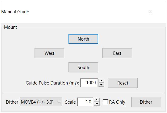
With the target framed correctly it is time to start the guider.
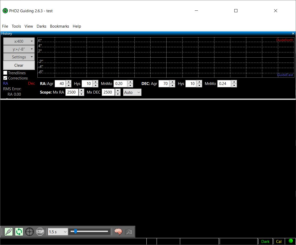
If you are using the Panther Mount with Telescope rOTAtor it must be reset and switched on now.
Open the guide screen by clicking the guide Icon
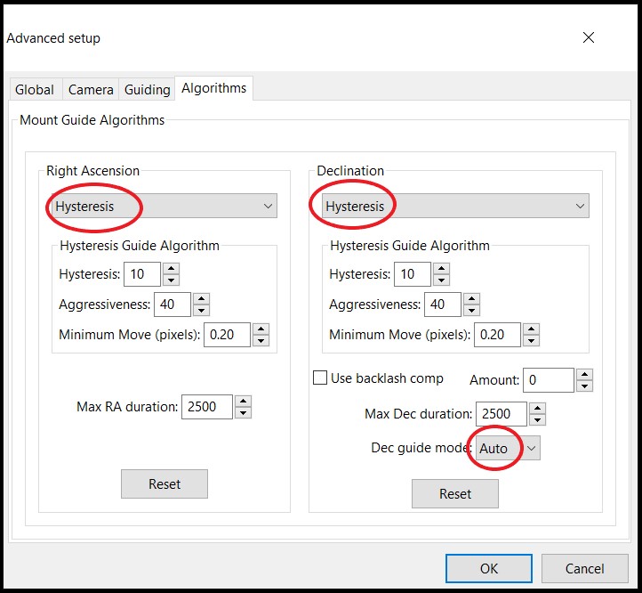
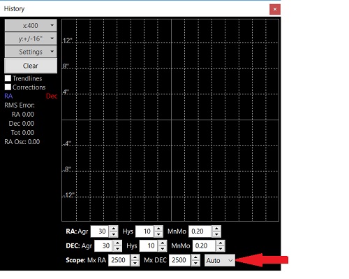
IMPORTANT for Alt-Az mounts. DEC mode must be set to Auto
Set the exposure time around 1-2 sec
Click the “double arrow circle” icon to start taking guide pictures.
IMPORTANT FOR ALT-AZ MOUNT GUIDING:
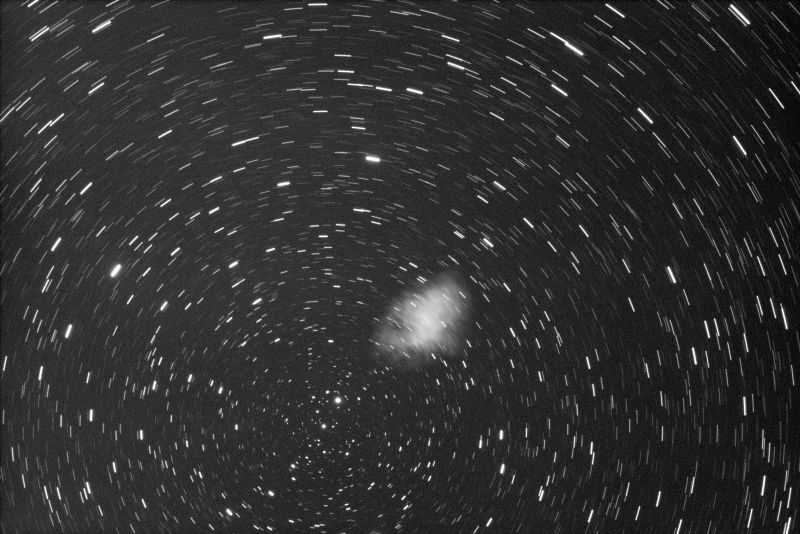
You must select one single star as guide star. Don’t let the APP select multiple stars for guiding. The field rotation will rotate the selected pattern of stars making guiding impossible.
If you use the Panther Mount with Telescope rOTAtor there is no visible field rotation and the guider can work on multiple stars. The illustrations below is made this way with multiple stars.
Click Guide icon. AAP will select a number of stars (marked with green circles) and start calibration (remember to pick just one if you use a normal Alt/Az mount)
If the APP starts to guide immediately it re-uses old calibration data and that is (most times) not good.
To force calibration you must clear the previous calibration data. Click the I – icon.
The Info-screen shows you how the calibration looks. Press CLEAR to force a new calibration.
After the calibration the AAP will begin to guide the mount. After some seconds to settle, you can see the RMS of the guide accuracy.
Adjust aggressiveness as needed to obtain the best guiding – exactly as on any other mount. Generally you can use the same values every time but the seeing can have influence on this.
Using “AUTORUN MODE” to take a number of subs
The telescope is now tracking the object precisely and the real imaging can begin. It is possible to use either “LIVE MODE” where the images are stacked and displayed on the fly or “AUTORUN MODE” where it is possible to set up a sequence of exposures to be taken and saved for later processing. Setting up the Autorun Mode is very straight forward and is independent on the mount type. For a DSLR the setup is like this:
Select the AUTORUN mode
Select the “List” icon to open the AUTORUN settings.
Now the Schedule screen is displayed. Pay attention to the following settings:
The target name is shown based on the latest Goto object. The taget name is included in the filename of the subs.
Group by slot is related to Monochrome imaging so I won’t go into details about that.
Meridian Flip: This must be OFF for an alt-az mount.
Delay and interval can be set as you wish. If needed increase a bit to allow the guider to settle.
If you Turn ON “Shutdown ASIAIR” the APP will shutdown after completing the Scheduled subs. I had the mount powered from the APP so this conveniently switched everything off.
If you Turn ON “Goto Home POS” the APP will command the mount to PARK before shutting off.
Click the Box saying “Light” or the + to edit/add the exposure sequence.
Now the image sequence screen is shown. You can add more of these as needed and they will be executed after each other.
Select the type of Subs. Here “Light” is selected.
Set the exposure time
Set the number of subs wanted
Select the Binning of the camera.
That’s is. Close the window and press back to come to the main screen.
On the Main screen push “SHOOT” and the scheduled sequences will be executed. Be sure to have started the guider before.
That’s it. The system is now catching photons thousand of years old and can do that all night long.
I made the test and the screenshots for this article on a full Moon night in August 2021. Not at all good conditions for a DSLR camera without any filters. Never the less here is the resulting image.
It’s getting easier and easier to use Alt-Az mounts for Astrophotography (AP). You don’t have to bother with levelling and polar alignment, so you can setup very fast and easy. With the many new computer devices it is also possible to control the system remotely. Most Alt-Az mounts can be used for short exposure AP as they are. When you want to take longer exposures you need a field de-rotator.
In this article I will explain how you can use the ASIAIR Pro computer unit to automate the imaging process. Most things are general for any mount type but I will focus on the things that needs special attention when using an Alt-Az mount.
This PART 1 article will focus on making the cabling and setting up in the app. All this can be done indoor.
I hope you find the article interesting. If you have any comments or suggestions send me an email at nth@trackthestars.com.
Small dedicated computers to control your imaging session
If you are into more serious Astrophotography the amount of equipment needed can be quite overwhelming. A complete advanced AP setup could contain:
Mount, pier
Main telescope
Main imaging camera
Filter wheel
Electric focuser
Rotator
Guide telescope
Guide camera
USB hub
Dew bands
All this equipment need to be computer controlled to work together and often you would like to setup a sequence of actions, that can “run the show” while you get a rest or enjoy visual observations.
The usual way to do this is to use a laptop computer with several available USB ports. In many cases this is a very good way to handle the task, but bringing a laptop outside and handling all the cables can be troublesome. Therefore we have seen a number of special “astro computers” come to market. They can be mounted on the telescope, helping organising all the cables and allowing for remote wi-fi control. One example is the ASIAIR pro but others like Stellar Mate or Astroberry does the same. Dedicated Astro PC solutions are also available on the market. So there are many possibilities for Astrophotographers.
I decided to test the ASIAIR Pro on the TTS-160 Panther Alt-Az mount. In this post I will describe how to set it up and report the most important learnings. Even though I have used the Panther mount, most of the principles will be the same on other Alt-Az mounts. But the achievable results depends very much on the mechanical quality of the mount.
What is the ASIAIR Pro
The ASIAIR Pro (made by ZWO Optical) is a small computer unit based on a Raspberry PI. It has 4 USB connectors (2 USB3 and 2 USB2) for connecting equipment. Besides this is has a power hub with four 12V outlets that are software controlled. The unit is controlled from an app running on either a mobile phone or a tablet. When powered up the unit creates it’s own wi-fi network that you connect your device to and then control it from the app.
The idea is that you fix the unit to the telescope/mount so that it rotates together with all the other parts of the setup. All the USB cables can be fixed to the mount/telescope for a good and safe operation. The only cable going onto the rig is the 12V power cable. Everything else moves with the mount and telescope.
The ASIAIR Pro can control ZWO cameras and DSLR cameras. Other camera brands can not be used. For that other solutions like Stellar Mate or PC based solutions must be found.
The ASIAIR Pro (AAP) was mounted on one of the counterweight arm. This is a convenient position as it moves together with all the equipment that connects to it. Keeping the cables free of movement and pull is important to avoid connection issues. Some of the cables I have are it bit long so I needed to curl them up. New shorter cables would be good. Placing the AAP on the main OTA is also a good position.
Power connection
One cable goes from the 12V 3A power supply to the AAP. This is the only cable going onto the moving rig. Then the AAP power hub is used for distributing the power. One cable goes to the mount and one cable goes to the electronic focuser. The Canon cable runs on battery (for now) and the guide camera is powered over USB.
For users of the Panther mount: Power for the mount head and the rOTAtor must come from one 12V outlet on the AAP using the split cable.
USB connections
The AAP has two USB3 and two USB2 connections. Actually none of the devices to be connected needs USB3 so they could be plugged in more ore less randomly. I decided for:
Mount and electronic focuser on USB2
Canon 6D and ASI224MC on USB3
Setting up in the ASIAIR app (first run only)
The first run setup I suggest doing indoor to learn everything nice and quietly. All the settings are stored on the unit so you just need to do this one time.
When all connections are checked the AAP can be powered up. After a few seconds it bips and is ready for use.
Open the ASIAIR app (available for IPhone and Android) and make the following setup:
Main camera settings
Select the main imaging camera from the drop down list. The camera is only visible if connected and powered up.
Input main telescope Focal Length. This value will be updated after the first plate solve to get it more precise.
The other settings are camera dependent and not important here.
Guide Settings (one special settings for alt/az mounts)
Select the guide camera from the drop down list.
Input guide telescope Focal Length.
Input camera gain. This setting depends on you guide camera and guide telescope but Medium is a good starting point.
Calibration step. This setting depends on your mount. For the Panther Mount 2000ms is fine and a good starting point for most mounts. If to few (lest than 5) calibration points are available decrease this number. If the calibration takes long time (several minutes) increase this number.
The guide speed can also be setup on many mounts. On the Panther mount 5″/sec is a good setting.
Max DEC, Max RA duration. On an alt/az mount altitude works as DEC and Azimuth as RA. 2000ms is a good value here. Play with it if needed.
Auto restore calibration. It is important to switch this OFF when you use an alt/az mount. It means a calibration will be made every time a new target is selected. This will ensure optimal guiding at all times. (If not switched on AAP will adjust and re-use the calibration data based on the mount DEC. This will not work on an alt/az mount).
Guide stability and Dither settings can be set as you wish independent of mount type. I will not go into details here.
Telescope Settings
Select the Telescope – Mount from the drop down list. The Mount is only visible if connected and powered up. Select the driver matching your mount. For the Panther Mount use “Meade ETX90/105/125/LXD75” and baud rate 9600.
Meridian flip settings: No need to worry about these settings with an alt-az mount.
Goto Auto-Center: If you switch this ON AAP will use plate solve to center objects precisely. The exposure time for the short exposure to be plate solved is set up. Often 1 sec is a good value, but if very few stars are visible increase the exposure time.
The filter wheel is not in use.
Electronic focuser
Select the Electronic focuser from the drop down list. The focuser is only visible if connected and powered up.
The other settings for the EAF focuser is out of scope for this post.
If you don’t have an electronic focuser you can just focus manually.
This completes the settings that must be completed before you can start taking pictures with the AAP.
In the next PART 2 article I will bring the system out under the sky and start guiding and taking pictures of Deep Sky Objects.
Summing up
Setting up the AAP for use with an Alt-Az mount is almost identical to setting it up for a polar aligned mount (German Equatorial). There are only 2 things to focus on:
Meridian flip settings: Don’t worry about these settings. Meridian flip will not happen on an Alt-Az mount.
Guide settings – Auto Restore Calibration: This must be switched off to allow for calibration of the guider for each new target.
In the autumn of 2020 I noticed quite a few great astrophotos on Instagram from @azastroguy. All the images were taken with a Panther telescope mount in Alt-Az mode. The guy behind these great images is Mark Johnston of Scottsdale, Arizona. I asked Mark if he could tell a little about his images.
Yes! I have been an active amateur astronomer for decades but only began my first astrophotography in June 2020, so keep in mind these photos were taken by a relative beginner. 100% of my photos are taken with the TTS-160 Alt Az mount. First of all, I’d like to say the mount is awesome as a visual mount. Portable, rugged, easy & quick to set up and tracks perfectly once aligned. But does it work for AP?
I live in Bortle 7 light-polluted suburb but despite that have managed to get some excellent photos using fast CCD cameras and Sharpcap live stacking. An Alt Az mount does create some limitations. Due to field rotation, you are limited to ~32 second maximum exposures, and about 30-40 minutes total exposure depending upon the telescope focal ratio, camera used and size of the target. Here are some examples of photos I have taken with either a 5.5″ F7 or 4″ F5 APO, the TTS-160 and a ZWO camera. The galaxies were taken at a dark site, but the nebulas from my backyard. In all cases the total exposure was less than 30 minutes, often 15-20. I plan to acquire the Track the Stars rOTAtor, and will begin to experiment with longer exposures. More examples of photos taken with the TTS-160 can be seen on my Instagram @azastroguy.
Mark Johnston.
Below are some of Mark’s images. They are good examples of what can be achieved with an Alt-Az mount while keeping the process simple. With a setup like this you don’t need to level or polar align your mount and no autoguiding is needed. Just point and shoot.
If you feel like you want to do more you can always add a rotator to your Alt-Az mount and move on to long exposure astrophotography.
When observing and imaging the moon, the sun and the planets you need a mount that can track the object fairly precise. Generally speaking you can use either an Alt-Az mount or an polar aligned mount (GEM or fork). Here I will look at how an Alt-Az mount can be used and how it compares to a polar aligned mount for this kind of observations. It is important to remember that an Alt-Az mount is not necessarily (even though it often is so) of a lower production quality than a polar aligned mount.
Setting up for planet observations
Setting up and Alt-Az mount is faster and easier than setting up an polar aligned mount. The basic steps are:
Setup the tripod/pier and mount head
no leveling needed
no polar alignment needed
Install and balance the telescope
only one axis to balance
Slew to the object and start the tracking
align on just one object
can be done as soon as the planet becomes visible in the twilight – or the sun in daylight
On all aspects easier than using a polar aligned mount.
Tracking the planet all night
As soon as the mount has been pointed at the object, it can begin to track the object. During the observations you will experience the following:
Eyepiece will stay in the same good angle for observations all night long. This also makes the use of “Atmospheric dispersion devices” easier as they have to be adjusted horizontally only once (see more below)
It is possible to track an object all night without the need for performing meridian flip
Field rotation will be in action but will not be visible either visual or photographic (see below for details)
Using an Atmospheric dispersion corrector for Planet observations
In these years Jupiter and Saturn are far south in the sky placing them very low in the sky for northern observers. It will be like that for some years to come, so it might be a good idea to consider using an Atmospheric Dispersion Corrector.
Atmospheric dispersion is a result of the earth atmosphere acting like a huge prism. It means light of different colors will be bend differently when passing through the Atmosphere. When looking at a star or Venus low in the sky this color separation is obvious.
The dispersion effect is always vertical – perpendicular to the horizon. Therefor this effect will stay in the same angle in the FOV of an Alt-Az mounted telescope – opposite to a polar aligned telescope. This splitting of the colors ruins the picture we see in the telescope. The lower the altitude of the object the worse this gets. Luckily there is a tool that can decrease (not remove) this effect, improving what we see quite a bit.
Atmospheric Dispersion Corrector
An Atmospheric Dispersion Corrector (ADC) works by introducing an adjustable prism in the telescope light pass that makes the opposite bending of the light to what happens in the earth atmosphere. In other words it brings the colors back in order. As the magnitude of the dispersion depends on the object altitude the prism needed to correct for this must be adjustable. In most ADC units this is achieved by having a split prism with two parts that can be rotated relative to each other.
When using an ADC the principle is:
Rotate the unit in the focuser until prism correction direction is vertical (on the ZWO ADC unit shown above a small bubble level helps)
Looking at the planet in the eyepiece or on the screen, adjust the correction factor until the best correction is seen
Once in a while it is necessary to re-adjust the unit because the object moves
The vertical angle must be adjusted regularly if the telescope is mounted on a polar aligned mount. If the telescope is mounted on an Alt-Az mount this is not necessary.
The correction factor must be adjusted as the object altitude changes.
Image from Sky at Night Magazine article – click on image to read article
Field rotation – and the influence on planetary imaging
Above we have seen that using an Alt-Az mount for planetary observations has a number of advantages over a polar aligned mount. But as you perhaps know Alt-Az mounts results in field rotation when tracking an object over time. Learn about field rotation here
Max acceptable field rotation between sub frames to be stacked
First we look at what kind of angular rotation we can allow between the first and the last frame in the video clip we take. The two largest planets Jupiter and Saturn has an apparent diameter of around 45 ” (for Saturn this is the rings). If we work with a camera resolution of 0.2″/pixel the math will look like this:
So this means that a field rotation of 0.5 degree will move a point on the edge of the planet 0.2 arc-second. For Mars this will be 1 degree because the apparent diameter is about the half.
How long time can you image keeping field rotation out of scope
The size or speed of the field rotation depends on the observers latitude on Earth and the objects Azimut and Altitude. It is possible to make precise calculations of this but to keep it simple I have prepared a table giving the needed information:
Minimum possible exposure time in seconds
Reading the table:
In the left column find the latitude closest to your location
In the upper row find the declination closest to matching the planets declination
If you are on a southern latitude select the declination with the opposite number of what it is.
Read the exposure time in the selected cell.
Important comments:
The time given is absolutely minimum. In most cases you can expose longer time.
If you live north of latitude 45 you can always image well over a minute. This is already the limit for Jupiter due to the planets own rotation (0.2″ is rotated in 50 secs).
If you observe from near equator, the planet can get close to zenith. A “dead zone” of 5 degrees radius has been taken into account.
For the expert imager there is a perfect solution to eliminate field rotation completely
If you are a really critical planetary imager you might want to expose for longer intervals than what is shown in the table above. If you do that you can use the WinJUPOS program to eliminate field rotation. WinJUPOS is mainly known for it’s capacity to de-rotate the planets own rotation to allow for longer total exposure times. But in the same workflow WinJUPOS can de-rotate the field rotation.
Comet Neowise 08. Juli 2020. TEC 140 f/7 TTS-160 Panther Mount. 3 sec exposure with Canon 1100Da. NLC covers the sky around the comet.Comet NEOWISE is making a great show right now. It passed closest to the sun on July 3rd and is now slowly moving away from the sun. This means we have to observe the comet very low in the sky. This is absolutely normal for comets but it put some demands on us observers.
1. Find an observation spot with a free horizon in the comets direction
Find the comet position for the planned observation time and find the Azimuth direction. TheSkylive.com is fine for this kind of planning. Using the Azimuth direction look at Google maps and find an observation spot where you have a free view in that direction. Google Streetview can help estimating the local horizon.
2. Bring your mount and telescope to the observation spot
Most telescopes and mounts can be transported to the observation spot but it is an advantage to have a setup that is easy to transport and setup.
3. Setting up and aligning
If it is in the evening twilight it is important to get started as soon as possible as the comet is setting soon after the sun.
Alt-Az mount
Setting up an Alt/Az mount in daylight is easy. Depending on the mount software there are different possibilities. Here is how I do it with the Panther Mount.
TTS-160 Mount ready and aligned
Set up the mount. No leveling or polar alignment needed.
Align on the sun before it sets.
Point to the sun (Alwayswith a solar filter on) and make 1st alignment. Often this will be precise enough as the comet is in the same area.
To improve the alignment you can wait 15 minutes and align on the sun again as 2nd alignment object. This will give a precise alignment.
Based on the first solar alignment it is possible to slew to a bright star (visible in daylight in the telescope) and use that as alignment object.
Align on bright star or planet
As soon as it is dark enough align on the first visible stars
Setting up a polar aligned mount during the day is difficult. All precise alignment principles needs stars to be visible. Here is what is possible to do:
Set up the mount head and level it precisely
Set the polar axis height on the mount to match your latitude
Using a compass point the polar axis towards north
When it is dark enough tweak the polar alignment as needed
4. Observing the Comet low in the sky
I observed and imaged Comet c/2020 F3 NEOWISE yesterday just 5 degrees above the horizon. As it was close to the sun the sky was not dark and the sky was covered with Noctilucent Clouds making the background extremely bright. Still I was able to see a nice split tail about 0.5 degrees long. The seeing never allowed for high power observations of the head. In the coming days I hope to have a chance to observe it in details.
Here is how I will observe the comet in the evening twilight
Having aligned the mount before sunset I will make a goto the comet position and watch when it will start to appear:
Head of comet Neowise. TEC 140 f/7, TTS-160 Panther Mount, ZWO ASI 224MC. Stack of 100 frames, exposure time 0.2 sec per frame.
In the brightest twilight I will observe the comet head at high power. The comet has the highest altitude at this time so the seeing will be best. If the comet head is bright you might try some lucky imaging (planetary technique) and see if you can catch jets coming out from the nucleus.
As it gets darker start to observe for fainter details in the coma
At some point the trade-off between comet altitude and darkness will give the best overall view of the comet. A good moment to take that wonderful comet portrait.
When the comet head gets close to the horizon try to observe the full length of the tail. A good time to image the the comet wide field.
And the morning twilight
The morning twilight is much easier to handle. You have all night to setup and prepare. BUT it is 3 am….
The winter sky with the many gas nebulas has disappeared in the western twilight. In an earlier post – Fast Deep Sky Imaging – I described how these large objects could be imaged with fast optical systems with limited focal length and large field of view. In springtime our view points away from the milky way arms and we get a free look to myriads of distant galaxies. Observing and imaging galaxies is a quite different matter as you can read in this post.
Galaxies and dark sky
For most unskilled visual observers Galaxies are faint hazy spots. If you try to observe galaxies from a light polluted place and don’t give you the time it takes to learn to really see these faint objects – all you will see is a faint spot – if anything at all.
If you instead brings your telescope to a rural dark sky place and take your time to really observe the galaxies you will realize that galaxies can show many details. It is possible to see spiral arms and dark dust bands.
Bring your telescope to a real dark
sky site to really enjoy Galaxies.
With the camera on the telescope this is a bit different. A dark sky is still a huge advantage but it is possible partly to compensate for a light polluted sky using filters and increased exposure time. But if you have tried to image from a dark site, you will now how much easier it is to get a good color balance and how much shorter exposure time you can use – or get much deeper with the same exposure time.
Bring your telescope to a real dark sky site to shorten exposure time and get clean colors
Galaxies and resolution
Besides for the two large exceptions M31 – the Andromeda Galaxy and M33 – the Triangulum Galaxy (and perhaps a few in the southern sky) most galaxies are rather small in the sky compared to gas nebula. Therefore we need to “zoom in” to get at better view.
Galaxies are small!
Compare Horse Head Nebula complex with Whirlpool Galaxy M51.
Visually this means more magnification. It is often seen that galaxies are observed with wide field eyepieces with low magnification. This might make the galaxies looks brighter but it is very difficult to see any details. In stead if the magnification is increased the sky will become darker and with careful examination more details within the galaxies will be visible.
I prefer to use magnifications around 75% of the telescope aperture in mm:
100mm telescope 75x
200mm telescope 150x
350mm telescope 262x
When you observe galaxies visually don’t be afraid to use a fairly high magnification.
Photographically resolution relates to image scale and aperture. The image scale has to be large enough to allow for the details to be recorded. To be able to get decent galaxy images an image scale around 1 – 1.5 arcsec/pixel is needed. So in most cases it means you will need a focal length around 1 meter or more. Increasing the image scale further will in most cases just lead to a fainter more noisy image with no extra details. When it comes to telescope aperture 100mm is minimum and 130mm and up is preferred.
Difference between image scale of 1.5″/pixel and 3″/pixel.
When you photograph galaxies aim for a pixel scale around 1-1.5 arcsec/Pixel
But remember tracking, focusing and seeing is usually what really sets the resolution limit.
A galaxy hunting starparty – all alone (corona time)
Luckily the lockdown in Denmark was not too harsh so it was ok for me to go to a rural place for an observation night. To really get the best of two worlds I brought both a visual setup and a photographic setup.
Short video presentation of Astrophoto setup
Astrophoto Setup
140mm f/7 (FL 980mm) TEC APO
Atik 460 sx camera with Baader LRGB filters
Televue TV60 as guide scope
TTS-160 Panther Mount with telescope rOTAtor
Short video presentation of Visual setup
Visual Setup
Celestron C9.25 SCT
13mm Televue Ethos Eyepiece, magnification 181x
TTS-160 Panther Mount
Visual results of the night
The sky turned out to be very clear and quite dark – very good for visual observations. I started in west and worked my way eastwards in the sky. Here is a list of objects I observed:
All Messier galaxies in Leo. The Leo triplet M65, M66 and NGC 3628 was fairly easy to see. The different shapes of M65 and 66 was obvious. NGC 3628 is large but with a much lower surface brightness.
In the Virgo cluster (in Virgo and Coma Berenices) I observed so many galaxies I can’t remember them all. I used Skysafari on my Iphone and just jumped from galaxy to galaxy. Amazingly most of the small (and to me unknown) NGC catalog galaxies were visible even though only as dim spots.
In Ursa Major I also observed many Galaxies and the Planetary Nebula – “the Owl”. The “eyes” were visible with adverted vision.
And just to mention a few of the “big ones”
The “Needle galaxy” NGC 4565. Stretching across the central FOV with an outer shape as know from images. Not certain I could see the dark dust band.
The “Black Eye Galaxy” M64. Large elongated and getting brighter towards the central parts. The dark dust cloud (the eye) visible with adverted vision.
The “Whirlpool Galaxy” M51. The two galaxies are very easy to spot close together. In M51 there are lots of dark areas outlining the spiral arms. Quite large in the FOV.
I ended the night observing Globular Clusters. M13 was amazing resolved to the center.
Astrophotos from the night
While I enjoyed the sky visually the AP rig was gathering photons. The main target of the night was “Markarians Chain of Galaxies”. The following subs were taken:
23 x 300 sec in Luminance
5 x 300 sec in RGB
I ended the night by taking sky flats against the morning twilight sky.
Markarians Chain – click on image for large size.
Before the morning twilight I also shot M13 – 8 x 120 sec in RGB – click on image for larger size
PHD2 is a fantastic tool for guiding our telescope mounts. Most of the basic features and settings were created with a German Equatorial Mount in mind. Using it with an Alt-AZ mount is just as precise, as long as you have the right settings.
In this post I will explain how to setup PHD2 when using an alt-az mount with special focus on the Panther mount, but the general aspects will be the same for all Alt-Az mounts.
Two simple terms you need to know
PHD2 was created with Equatorial mounts in mind. Therefore PHD2 uses the terms Right Ascension axis and Declination axis. When guiding an Alt-Az mount:
Azimuth is equal to Right Ascension AZ = RA
Altitude is equal to Declination ALT = DEC
How to connect the mount to PHD2
There are two ways to connect the mount and PHD2:
Using the ST4 interface.
To use this principle your guide camera must have a ST4 compatible guide port. All dedicated guide cameras has this type of port. Connect the ST4 port on the camera to the AG port on the mount head.
Using PC interface and ASCOM driver
You must install the ASCOM platform and the Ascom driver called: “Meade LX200 Classic and Autostar #494, #495, and #497” Use a USB-to-Seriel adapter and the PC cable to connect the USB port on the computer to the PC port on the mount head.
ALWAYS connect ALL the cables before powering up the mount. Then power up the mount, align it and leave it in the operation screen.
Setting up PHD2 for Alt-Az guiding
Start PHD2 on the PC.
Before starting to guide it is necessary to adjust some settings. In this article I will focus mainly on the settings that are important (different) when using an Alt-Az mount. I recommend you look at the user manual for PHD2 for a general description of the other settings.
This screen is shown at startup.
Click on the brain.
A new window with four tabs pops up. We will look at two of the tabs – guiding and algorithms:
In the Guiding Tab be sure to adjust these settings:
“Use Dec compensation”
If you use the ST4 connection this setting must be ON
If you use the PC/ASCOM connection this setting must be OFF
“Reverse Dec output after meridian flip”
Alt-Az mount do not flip. Must be OFF
In the Algorithms Tab be sure to select:
“Hysteresis” on both Right Ascension and Declination.
On an Alt-Az mount both axis are tracking all the time. Therefore both axis must be guided as the RA axis on an equatorial mount. There is no backlash on an Alt-Az mount when guiding because the motors are never reversed.
“Auto” as Dec guide mode – this is to allow guiding in both directions on the Alt axis.
Lets connect the equipment in PHD2
Click on the connector icon in the bottom left corner.
The Equipment connection window pops up.
Select camera
Select the guide camera you use
Select Mount – if you use the ST4 connection do like this:
Mount: Select ON CAMERA
Aux Mount: Select ASK FOR COORDINATES
Select Mount – if you use PC/ASCOM connection do like this:
Mount: Select Ascom driver: Meade Classic and Autostar I
The port number of the seriel comm port on the PC must be correct. Click the toolbox icon to see the Ascom driver setup window. Change port number if connection is not succesful.
Aux Mount: None
When camera and mount is connected PHD2 will show this screen:
Ready to calibrate the guider and guide
Calibration is the process where PHD2 moves the mount small distances in each direction and take images at each position. Based on this the PHD2 learns how the mount response to the guide commands and the finds the camera angle. Calibration is a completely automated process that only takes about a minute to perform.
Here follows the things you must be aware of to get a good calibration and a good guiding performance (again with main focus on the things related to Alt-Az mounts):
Focus guide telescope carefully
On the Panther Mount guide speed should be set to 10″/sec (this is selected in the setup menu)
The Altitude of calibration star must be considered:
Calibrate at an Altitude of 30-40 degrees
When starting the calibration process PHD2 will ask for the Declination – input the ALTITUDE – no decimals neededif you use the ST4 connectionDec compensation is available. Therefore:
if you use PC/ASCOM connection Dec compensation will not work. Therefore:
Calibrate on the same altitude as the target (just use actual guide star). If target is above 75 degrees in altitude calibrate at around 75 degrees.
Calibration must be performed for each target if altitude changes more than 10-15 degrees. It only takes 1 minute to calibrate so why not.
Just “Push Here Dummy” to start the calibration and guiding.
Appendix: Indoor testing of connections
Manual guide test at daytime/indoor
When setting up new equipment it can be nice to complete as much as possible indoor not wasting clear sky. So when you have installed PHD2, Ascom and made all the settings it is nice to see if it works.
If you connect camera, mount head and the PC, you can follow this procedure for a basic check. If any step fails fix it before you move on:
Align the panther mount with a “fake” alignment. Just pick any star (or the sun) that you know are above the horizon and make a one star alignment on it. The mount can point anywhere. The mount will now track and show steady equatorial coordinates (of the alignment star)
Connect Camera in PHD2
Connect mount – On camera if ST4 cable – Ascom driver if PC cable
On the main PHD2 screen select the menu item “manual guide”
Now push one of the buttons. If you watch the Panther handpad you will see the coordinates change. We are talking few arc-seconds. And be aware that Right Ascension is displayed in time seconds – not arc-seconds – so the movement will be much smaller in RA.
You must be able to see a movement in all four directions. No conclusions can be made on how much movement is seen, because that depends on other parameters not known in this test situation.
To many clouds – to little clear sky – what can you do
In Denmark we have few clear nights and from May to August we have light summer nights. So the nights where I can image the sky – as I love to do – are few.
What to do about it?
Some people invest in remote observatory facilities – but that is not really me. I enjoy to much being out with the telescope under the clear sky.
Instead I decided to try how I can get the most from the limited clear sky hours I have. The focus has been on:
A fast optical system
A pixel scale to give best sensitivity
One Shot Color camera to keep things simple
A setup that is easy to transport and fast to setup
Going to a dark sky location to get the best signal to noise ratio
Based on this I assembled and tested a setup during this autumn and winter.
A fast optical system
Wanting to get a really fast optical system quickly limited the possibilities. Telephoto lenses can be very fast but only for short focal length. As I wanted more focal length there were two (affordable) options:
I am not able to say which of these solutions are the best, but I was so lucky that I got the chance to borrow a Celestron C9.25 with a hyperstar system from a friend. A great possibility to try things out.
The C9.25 in hyperstar configuration has a focal length of 540mm and focal ratio f/2.3.
A pixel scale to give best sensitivity
Speaking in general terms a larger pixel size will increase the Signal to Noise ratio, as more photons will hit each pixel (I am aware that there are many other aspects to this but for now we keep things simple). So as large pixels as possible..
But resolution must be considered too. With a typical best seeing around 2″ where I observe from, the general rule of thumb (and Nyquist Theorem) says I should aim for a pixel scale around 1″/pixel. But I aimed for larger pixels to get the highest sensitivity.
Again a good friend wanted to join this experiment and offered to let me try his ZWO ASI071MC Pro camera. With a pixel size of 4.78 x 4.78 um the pixel scale ends at 1.84″/pixel. Quite a large number but I decided to test this combo out.
And the ASI071 camera is a cooled One Shot Color camera meeting that request too.
A setup that is easy to transport and fast to setup
The Celestron C9.25 is a good transportable telescope. With an OTA weight of around 10 kg it is easy to handle and install on the mount. And it still offers a quite large Aperture.
For guide scope I used a TeleVue TV60 with a ZWO ASI 224 camera.
With a little practice I was able to unpack the car and setup the system in less than 20 minutes and could be imaging 10 minutes later.
Complete setup ready at Avnø Starparty
Going to a dark sky location to get the best signal to noise ratio
I live in a suburban area where I can image from my backyard – even with One Shot Color cameras. But for this test, I wanted also to get the benefits from a real dark sky. Therefore I on a few nights, drove about 1 hour away from Copenhagen to dark sky sites. It was my plan to do that more, but this winter the clear sky has been limited to short spells, making it impossible to plan excursions. So quite often the backyard has been used for a quick setup and imaging a short time.
Results and learning points from using the setup
Setting up and starting up
The setup was as fast and easy to handle as expected. With the terrible weather the system really proved its worth. When the sky suddenly cleared unexpectedly I was able to setup the system and start imaging in less than 30 minutes. What made the setup fast was:
Fast setup without leveling needed
No polar alignment needed
Easy guiding with PHD2 using the same calibration over more nights
Easy and fast focusing using a Bahtinov mask and the software Bahtinov Grabber
Image scale, exposure time, filters
Examining the first images quickly showed that the pixel scale was a bit large (1.84″/pixel). Zooming in on a single star showed some degree of undersampling.
Zoomed in on central part of raw image stack. The fainter stars are quite pixelated
Therefore it was clear that this telescope/camera combination was usable mainly for large wide field targets. It was the targets planned from the beginning, but I would have liked also to image some smaller targets as well.
I tried several different exposure times for the individual subs. From 30 secs to 300 secs. And sometimes a combination was used to make HDR processing.
I also used two different filters: IDAS LPR filter and Baader IR Cut filter. The LPR filter had a good effect on the image contrast when imaging under a suburban sky, but made little difference when the sky was really dark.
How fast can you take an image
It is always better to have longer total exposure time on a target to decrease the noise. So the lucky guys living where the sky is clear very often can use 10 – 20 – 30 hours for a single image. If I wanted 30 hours for one image it would mean one or two objects per year…
So in this small experiment I have tried to see how short the combined exposure time can be.
Here follows some examples of the images taken. All are taken with the setup described above and the camera at unity gain.
In order of increasing exposure time.
10 minutes total exposure time
M8 Lagoon Nebula, 10 min (10 x 60 s), IR Cut filter, Suburban sky – elevation 7 degrees
30 minutes total exposure time
M45 The Pleiades, 30min (30 x 60s), IR cut filter, Suburban sky
40 minutes total exposure time
M42 The Orion Nebula, 40 min (20 x 120s), IR cut filter, Suburban sky (central part made from shorter subs)
60 minutes total exposure time
Eastern Veil Nebula, 60 min (60 x 60sec), IDAS LPR filter, Suburban sky
80 minutes total exposure time
Horse Head Nebula, 80 min (40 x 120s), Suburban sky, IDAS LPR filter
Double Cluster and Comet Panstarrs, 80 min (80 x 60 s), IDAS LPR filter, Suburban sky
120 minutes total exposure time
Iris Nebula, 120 min (60x120s), Rural sky, IR Cut filter
M31 The Andromeda Galaxy, 120 min (60 x 120s ), IR cut filter, Suburban sky
Conclusion
The combined setup of the C9.25 Hyperstar and the Panther Mount is a very fast and effective imaging system. It is extremely well suited for many wide field targets. In the tests I have made the total exposure time has been limited, because of the typical weather conditions in Denmark. If you travel to better sky conditions, I am certain that longer integrations with this kind of setup, can give amazing results and catch very faint objects.
Using a camera with smaller pixels is among the things I would like to try out to see if smaller targets – like Galaxies – could be imaged successfully. Perhaps something I will try in the coming Galaxy season.
Thanks to Michael Rask for letting me borrow his C9.25 telescope.
Thanks to Niels V. Christensen for letting me borrow his ZWO camera and for processing many of the taken images.
At times it could be great to setup the telescope mount in daytime. Generally, this is not possible when you can’t see any stars. In this post I will describe a method to align the mount precisely in daytime.
Sometimes on a nice sunny day you would like to observe the sun or the brighter planets – Mercury and Venus. Unless you have a fixed installation in an observatory this can be difficult, as you can’t easily spot the planets with the naked eye. Using the principle described below, you will be able to align your mount during the day and make goto’s directly to the brighter planets and even the brighter stars can be seen in broad daylight.
The basic idea of using a terrestrial object I got from Claus Jensen, a friend and member of Copenhagen Astronomical Society.
Using the sun for daytime alignment is another well known option but I will not go into that method here.
Step-by-step daytime alignment of your Alt-Az mount (most brands)
Some preparations first
Find your favorite observation spot
Pick a good spot where you want to set up your telescope mount for later daytime observations
Mark the spot with marks for the tripod legs or a center point below the mount head
Your observation spot can be in your backyard, on your balcony or a remote location. As long as you go back to the same spot next time.
On a clear night do the following (this only needs to be done once)
Setup the mount and telescope on the selected observation spot
Be sure to level the pier precisely
Now make a precise stellar alignment as you usually will do
The trick – save a Terrestrial object
Using the handpad slew the telescope to a remote terrestrial object. Precisely center the terrestrial object in the field of view. Turn off celestial tracking while you do this. (It is ok to use a fairly close object if the mount is set up at exactly the same spot next time).
Now save this object in the handpad – and the mount is ready for daytime alignment. And remember you only need to do this once. Every time hereafter when you want to setup in daytime you can use this terrestrial object.
Take down telescope and mount.
Setting up for daytime observations aligning on terrestrial object
Setup the mount and telescope exactly on the selected observation spot
Be sure to level the pier precisely
Power up the telescope and perform a (cheat) one or two star alignment like this:
For many mount types you point the telescope towards north and set the tube horizontal. It is not necessary to do this precisely – just point no measuring needed.
Start the alignment procedure on the handpad. The mount will slew to the first alignment star. As you can’t see the star just accept the position without moving the telescope. If you selected a one star alignment skip to step 4.
The mount will slew to the second alignment star. As you can’t see the star just accept the position without moving the telescope. Now the mount believe it is aligned. But as we did not point precisely towards north and had the telescope precisely horizontal there will be some discrepancy.
Now make a goto to the terrestrial object you have saved earlier.
The goto will not place the object precisely in the center. So now you release the clutches on the mount and manually (don’t run the motors) center the terrestrial object. Lock the clutches again and the mount is aligned.
Now you can observe and track the sun, planets and stars just like at night!!
Step-by-step daytime alignment of your Alt-Az mount – TTS-160 panther
Some preparations first
Pick a good spot where you want to put up your telescope mount for later daytime observations
Mark the spot with marks for the tripod legs or a center point below the mount head
On a clear night do the following
Setup the mount and telescope on the selected observation spot – with the Panther mount there is no need to level the pier.
Now make a precise stellar alignment as you usually will do
Now save the telescope alignment for later use
Using the handpad manually point the telescope at a remote terrestrial object. Precisely center the terrestrial object in the field of view. Turn of celestial tracking while you do this. (It is ok to use a fairly close by object if the mount is set up at exactly the same spot next time).
In the handpad menu select PARK function. This saves the actual scope position.
Take down telescope and mount.
Setting up for daytime observations re-using the night alignment made earlier.
Setup the mount and telescope on the selected observation spot
Using the handpad slew the telescope to point at the same remote terrestrial object used at night. Precisely center the terrestrial object in the field of view.
In the handpad select “Load last alignment“.(As the telescope is pointed in the same direction as when parked the mount will know where it is pointed.)
The mount is now aligned and goto’s any object can be made.
If you want you can refine the alignment by aligning on objects visible (found by goto).
When finished observing the mount can be parked on the terrestrial object again to be ready for next observation Session.
Now just enjoy daytime observations in the warm sunlight
Summing up
Normally aligning your telescope mount in daytime involves using the sun as alignment object or trying to get it done using bubble level and compass.
Using a terrestrial object to align your telescope in daytime is a simple and very accurate method. It can be done fast and will give you new opportunities to come out and observe with your beloved telescope.
This is a video recording of a talk about the Modern Alt-Az mount held at The Practical Astronomy Show in March 2019. Actually the recording was made a few weeks later when I repeated the talk at The Astronomical Society of Copenhagen. Unfortunately the video quality is not perfect but I hope it can be useful anyway.
The video is rather long so here are the timing if you want to jump to certain sections:
Introduction
My Journey into amateur astronomy (01:24)
Comparison of Polar aligned and Alt-Az Mounts (05:05)
You can take great astrophotos using your Alt-Az mount – learn how here
If you own an Alt-Az mount, you most likely think “It cannot be used for deep sky astrophotography”. But that is not correct. It is possible to take wonderful deep sky images with an Alt-Az mount if you know how to do it and pick the right objects. As with any astronomy equipment, the quality of the mount (stability, tracking accuracy), telescope and camera will of course have influence on the final result. But with good knowledge and persistence, you can take great images even with modest equipment. This article will explain how.
In this post, I will look into the following subjects:
With limited exposure time per sub, the following is important:
A fast optical system to get as much data as possible, preferably f/5 or faster..
A camera with low readout noise (likely a CMOS camera – but most modern cameras can be used)
A mount that can track precisely (guided or unguided) for 1-2 minutes.
A PC with good hard disk capacity as many subs must be stored
Many systems can meet these criteria. So just start with the equipment you have.
Alt-Az mount tracking
Good tracking is important when taking deep sky images. The needed accuracy depends on the focal length, but often we talk sub arc second tracking. To get the best tracking, the mount must be aligned precisely. For most Alt-Az mounts, leveling of the pier is not needed, but check the manual of your mount. When the mount and telescope have been set up, be sure to balance the mount correctly (see more here). With only one axle to balance, this is very easy. A little off balance in the Alt-axle is ok to ensure that any backlash in the system is held to one side.
When aligning the mount on two or three stars, it is important to center the stars precisely. Use a crosshair eyepiece or the camera live view.
Guiding an Alt-Az mount
The guiding principles for an Alt-Az mount are almost the same as for other mount types:
Guiding can be done through a piggy backed guide scope or off-axis through the main imaging telescope
Piggy backed guide scope
Guide signals can be sent to the mount through a ST4 guide port or as pulse guide through the PC(ASCOM) interface
Any of the available guide software programs should be able to do the job (I can recommend the free PHD2 guide software. It works perfectly)
Calibration and adjustment of the guiding routine parameter is basically the same as for other mount types.
But there are still some areas to look at and understand when guiding an Alt-Az mount:
When an Alt-Az mount tracks an object, the drives on both axles are running continuously . This makes the guiding very stable, because the motors never need to reverse direction. It is only the speed that is adjusted in the same direction meaning that there is never an issue with backlash.
The Azimuth axis will by the guide software be seen as the RA axis on a polar aligned mount. This is OK.
The guide software will see the Altitude axis as the Declination axis on a polar aligned mount. This is OK but the following must be observed:
on a polar aligned mount, the Declination motor is only started when a correction is needed. If the direction is changed, backlash will come into action. Some of the guiding software programs have special routines to help with this problem. These routines must be turned off and the guiding of the Altitude axis must be done exactly as the guiding of the RA.
PDH2 Guide window. Notice DEC/ALT axis set for AUTO
When picking the guide star, it must be as close to the imaged object as possible. If the distance is large, the guider will try to compensate for the field rotation and that will cause problems.
Having the right setup in the software guiding an Alt-Az mount is just as easy as guiding a polar aligned mount.
Influence of field rotation – where in the sky to point your camera
Field rotation is the reason for not taking long exposure astrophotos with basic Alt-Az mounts. But if you understand field rotation, you can work your way around it and get all the advantages of the Alt-Az mount.
When the mount is tracking precisely the guide star will stay in it’s fixed position. What happens over time is that the rest of the FOV will rotate around the guide star (se explanation of field rotation here). This means that a long exposure image will look like this.
600 sec exposure. Notice the used guide star is in the centre of the arcs
To get nice round stars all over the image, the exposure time must be reduced. The task is to find the longest exposure time that will give perfect tracking and round stars all over the FOV.
A precise calculation of this is quite complicated as the speed of the field rotation depends on the observers latitude and where in the sky the object is placed. On top of this, we must look at the size of the camera sensor (diagonal measurement) to see what influence a certain rotation angle will have in the corners of the sensor. But notice that the focal length of the imaging telescope has almost no influence on the effects of field rotation. I will not go into details with these calculations here (comes in a future post) but provide a table with good standard exposure times.
How to read the table:
Find the table that covers the latitude you observe from
Find the Azimuth of your object in the left column and the altitude in the row at the top
Look in the selected cell and find the number of seconds you can expose a single sub
Notice the following
Imaging in east and west gives access to longer subs
The possible exposure time is less high in the sky
Starting with the exposure times from the table will give you good results. Try also longer subs as the numbers are conservative.
Here is an example of different exposure times:
Orion Nebula, single 30 sec raw frame, TEC 140 APO f/7, GQS6120, TTS-160 Panther Mount
Below is a crop of the bottom right corner of the image with different exposure times.
When these images were taken the Orion nebula was in south and about 30 degrees in altitude. I am imaging from Latitude 56 degrees north. Looking in the tables above the suggested exposure time is between 21 and 26 seconds. This matches the shown results well as it is possible to see a little elongation of the stars in the 30 sec exposure.
Good objects for short exposure subs
When selecting objects for short exposure astrophotography, there are two things to be aware of:
most important object surface brightness
You must target objects that have a good surface brightness. Surface brightness is a measure of how much light we receive from the object per area. It means that the number of photons that hit one pixel on our camera depends on this. As an example, the Triangulum Galaxy M33 has a combined magnitude of 7 but is a very large galaxy (1 degree in diameter) leading to a surface brightness of mag 22.3 per square arcsecond. The Ring Nebula M57 is only magnitude 9, but is quite small (1.3 arc min in diameter) and hence has a surface brightness of mag 18.8 or 25 times brighter than M33. If you try to observe these objects visually, this is quite obvious.
object size
It is an advantage to image smaller targets that will only take up the center of the FOV. This will allow for longer subs as the corner of the FOV can be cropped away.
Good objects to start with are: Orion Nebula M42, Dumbbell Nebual M27, Ring Nebula M57, Whirlpool Galaxy M51, The Eskimo Nebula NGC2392. But there are many more so just do it.
Taking the subs
Having the mount, telescope, guide telescope and camera ready, there are a few steps to go through to acquire the images:
Align mount
Focus camera – using a bright star close to the imaging target is often a good idea
Centre the target object – frame as wished
Calibrate and start the guider
Take the subs with the estimated correct exposure time
Continue until the object sets – no meridian flip is going to stop you.
It is not within the scope of this article to go into details with the above list as it is standard for any kind of deep sky imaging. But feel free to ask any questions at the bottom of this page or send me an email.
Aligning and stacking the subs
Here is an example of typical raw subs from when I am out imaging.
30 sec sub TEC140 f/7, QSI6120 Luminance, TTS-160 Panther MountSame setup as the picture above. Taken 57 minutes later
This is M1 – the Crab nebula. In this session, I took 200 x 30 sec subs. As you can see the subs are rotated in relation to each other due to the field rotation.
Aligning these subs is just as easy as any other non-rotated subs. Standard image processing software handles this flawless. I have used the free Deep Sky Stacker with good results. Today, I use PixInsight as I always use this for all the image processing afterwards.
Here is the aligned and stacked M1 picture before any processing is done.
You may have learned that for taking good astrophotos, you need a polar aligned mount preferably a german equatorial mount. But with new high quality Alt-Az mounts, this is no longer true. New technologies introduced in Alt-Az mounts mean they can deliver precise equatorial tracking while maintaining the basic advantages of the Alt-Az mount (read more about these advantages and a comparison to Polar aligned mount here).
Tracking needed for precise astrophotography
One of the first challenges when taking astrophotos is to achieve good tracking. Without good tracking of the object imaged, the rest doesn’t matter. Top quality optics, super sensitive low noise camera, everything collimated and aligned perfectly – all this will not help you if the tracking is bad.
Tracking the sky means that the telescope must continually be pointing at the exact same point in the sky. The stars rise in east and set in west and the telescope mount must have a movement pattern following them all the way.
The polar aligned parallactic mount handles most of this in the setup process. After carefully aligning the polar axis to be parallel with the Earth rotation axis, it is possible to track the sky by rotating the Polar axis at the correct constant speed. A solution that made it possible in the old days to have a mechanical clock running the mount. And the alignment of the polar axis also secures that no field rotation (explained below) takes place. But leveling and polar aligning the mount takes time and is not always easy.
The Alt-Az mount calculates the movement pattern in the alignment process. The mount can be setup without any leveling of any kind. When powered up, the mount is aligned on two known objects creating the information needed for precise tracking of the sky. Based on that information, a basic Alt-Az mount can track a single object across the sky with great precision. The movement pattern of the basic Alt-Az mount will on the other hand result in field rotation. Setting up and aligning an alt-Az mount is very simple to do – a lot easier than polar aligning a GEM.
Field rotation
Field rotation principle.
If you watch the half moon rise in east, you will typically see the moon terminator at an angle not being vertical. If you look again later when the moon has reached south (or north), you will notice that the terminator now is vertical. When the moon reaches the western horizon, the terminator is again angled to the horizon and in the opposite direction to when it rised in east. This phenomenon where the sky changes its angle to the horizon is called Field rotation.
The Alt-Az telescope mount moves around a vertical and a horizontal axis. Therefore, a camera placed on an Alt-Az mount will keep it’s angle in relation to the horizon and terrestrial objects. But if you point the camera at the moon and takes 3 images: in east, south and west the moon will have different angles on the pictures even though the mount has tracked perfectly and kept the moon centered in the pictures.
In a coming articles the details of Field Rotation will be covered in details.
Long exposure astrophotography with Alt-Az mounts
With modern technology it is very easy to eliminate field rotation and achieve true equatorial tracking with Alt-AZ mounts. And with the fast technological development within astronomy equipment this is continuously getting even easier. To eliminate the field rotation two solutions are available today.
Alt-Az telescope with camera rotator (Planwave CDK700)
The first solution is the introduction of a camera rotator. It is a device installed on the telescope allowing for automatic rotation of the camera around the optical axis. When tracking the sky this rotator will track the field rotation exactly as the mount tracks the azimuth and altitude. This is the solution used on all larger professional telescopes and some larger amateur telescopes. Using the camera rotator also adds the advantage that the framing of objects and picking of guide stars can be done remotely/automatic. When using a camera rotator guiding must be done off axis through the imaging telescope. Several companies are offering camera rotators.
Optech Pyxis 3″ rotatorMoonlite Night Crawler focuser/rotatorTelescope rOTAtor (Track The Stars)
The second solution to eliminate field rotation is the Telescope rOTAtor. It is an invention I made for the Panther mount from Track The Stars. The idea is to rotate the entire telescope OTA on the mount including any piggyback mounted equipment. The basic functionality is the same as the camera rotator – when the mount tracks an object the Telecope rOTAtor tracks the field rotation.
The main difference from the camera rotator is that a piggybacked guide telescope can be used for guiding and a piggybacked DSLR camera will also track the sky equatorially. For a transportable setup, this can be a great advantage.
Alt-Az mount with rOTAtor
The Telescope rOTAtor has a certain rotation angle and must be reset every 1-3 hours depending on where in the sky the object is located. It is possible to take single subs as long as you normally want (up to 1 hour or more). For a large total integration time, the rOTAtor must be reset as needed.
The quick and easy way of stacking short subs
If you are new to astroimaging or just want to have the easiest solution at the telescope, stacking of multiple short exposures might be the way to go. All you have to do is setup and align your mount. Then focus and frame your target. Now, you can start taking short subs. If you keep the subs short, no guiding is needed and field rotation will not show up on the individual subs (more on this in a future post). Typically, you can have subs up to 30 seconds without any visible field rotation and if you image in east and west your subs can be much longer. Of course, the unguided tracking accuracy of your mount must be
NGC891 800x10sec TEC140 f/7 refractor, ZWO ASI224 camera, Panther Alt-Az mount, no rotator, no guiding
taken into account too. To get the best resolution, you can guide the mount to get the most precise tracking.
The subs will of course show field rotation between the frames, but most of the stacking software programs available will handle this and align the images perfectly. With the new low noise cameras, very impressive results can be made using this simple principle.
In the coming posts, I will go into more details with these different astrophotography techniques. Stay tuned.
The Alt-Az mount is gaining fame again after many years in the shadow of the polar aligned parallactic mount. The ever increasing possibilities within computer control has made it possible to design Alt-Az mounts capable of delivering precise equatorial tracking. Having the simple mechanical principles of the Alt-Az mount, these new mounts offer easier transport and faster setup than the typical polar aligned mount.
Setting up an Alt-Az telescope mount – no leveling needed
Basically, an Alt-Az mount has a vertical azimuth axle and a horizontal altitude axle. However, this does not need to be precise with many newer mounts where the software handles the alignment. Therefore, the great advantage setting up an Alt-Az mount is that no leveling of any kind is needed. Just set up the tripod or pier and install the mount head. No need for bubble levels or compass directions.
Balancing the mount – only one axle to worry about
Balancing an Alt-Az mount.
When you balance an Alt-Az mount, there is only one axle to worry about. The Azimuth axle is vertical and hence needs no balancing at all. The altitude axle is balanced by sliding the telescope OTA in the dovetail saddle or tube rings. A piggybacked guide scope must most times be balanced with a separate counterweight on the OTA – though some Alt-Az mounts have counterweights that can handle this too (as shown in animation).
Balancing a German Equatorial Mount (GEM).
When you balance a polar aligned mount, there are two axles to worry about. Firstly, you balance the declination axle by sliding the telescope OTA in the dovetail saddle or tube rings. If a piggybacked guide telescope is installed on the main OTA, it is most times necessary to have a counterweight on the opposite side of the main OTA. Secondly, you balance the RA axis by adjusting the position of the counterweight.
Aligning the mount to track the sky – no more polar aligning
When the Alt-Az mount is setup and balanced, it can be sky aligned. For all available mounts, this is done by pointing the telescope at 1 to 3 known stars or planets. The way this is done in the hand controller can vary, but the basic function is the same: By measuring the position of the alignment stars, the mount software can calculate the precise setup angle and compensate for this to achieve precise goto and tracking, even though the mount was not leveled in any way.
This makes the Alt-Az mount so fast and easy to start up and alignment stars can be found in any direction making it unimportant if areas e.g. Polaris are covered by trees or buildings.
No more turning the telescope and eyepieces upside down
Movement pattern of Alt-Az mount tracking object from rise in east to setting in west.
The movement pattern of the Alt-Az mount is very simple. Around the vertical Azimuth axle, the telescope can swing 360 degrees making it point in any compass direction. Around the altitude axle, the telescope can swing from horizontal up to vertical.
This simple movement pattern has the advantage, that the telescope OTA always stays in the same angle . If you insert an eyepiece in a diagonal, it will keep the same angle when the telescope moves around the sky. If your finder telescope is placed nicely on top of the main OTA, it will stay in that position.
Movement pattern of GEM tracking object from rise in east to setting in west.
Compared to the polar aligned parallactic mount, this is quite different. Due to the fact that the polar axle is inclined, the telescope OTA will move in a pattern making the eyepiece and finder scope change positions so they are less comfortable to view in or sometimes impossible to view in without rotating them. On top of this, some Polar aligned mounts (German Equatorial Mounts) must perform a meridian flip when they pass south. This operation swings the telescope around so that everything placed on the top of the OTA suddenly is placed below the OTA. This is also a bad idea for the collimation of the telescope, as the mirror will lean towards the opposite side of the mirror cell.
Summing this up, it is clear that the basic movement pattern of an Alt-Az mount is better for the observer and the telescope.
Astrophotography with Alt-Az mounts – new possibilities
Almost everybody can agree that the Alt-Az mount has several advantages over the polar aligned parallactic mount as described above. It is very hard to see it differently.
When it comes to doing astrophotography, the situation is a bit different. An Alt-Az mount can track an object in the sky precisely, but the sky around the object tracked will over time rotate in the field of view. So using a basic Alt-Az mount (without rotator) for Astrophotography has some limitations.
But new technologies are changing the picture. New cameras with lower and lower read out noise are emerging. Therefore, short exposure astrophotography is giving better results and becomes more popular. The basic Alt-az mount is perfect for this kind of astrophotography.
M13, Basic Alt-Az mount (no rotator), 147x30sec
For many faint objects, long exposure subs are still needed. Again, the technology is giving new possibilities. By adding rotator systems – either rotating the main OTA or just the camera – to high quality Alt-Az mounts, long exposure subs are easily available. And all the earlier mentioned advantages of the Alt-Az mount are kept. Remember that all the big Pro telescopes work this way.
In the next article, I will look more into the Astrophoto possibilities with Alt-Az mounts. Stay tuned.
This is the first article in a small series that will focus on the use and possibilities of Altitude-Azimuth (Alt-Az) telescope mounts. First the basic overview will be created and in the coming articles more details on the actual use and possibilities of the modern Alt-Az mount will be covered.
The historic view
One of Sir Isac Newton’s first Newtonian telescopes on an Alt-Az mount.
The very first telescope mounts made were Alt-Az mounts. Logically, it is the easiest way to mount a telescope to get a compact and stable base. For astronomical telescopes, the need for tracking the objects across the sky lead to the invention of the Polar aligned Parallactic mount. In the times of no computer control, the fixed speed drive needed for the polar aligned mount was easy to make as a mechanical clock. With modern computer controlled drives, the same tracking across the sky can be achieved with the simpler and more stable Alt-Az mount.
Traditionally, the polar aligned German Equatorial mount has been seen as the best all round mount for the amateur astronomer, but that picture is changing fast with new improved Alt-Az mounts suitable for both visual observations and advanced astrophotography.
What is an Alt-Az telescope mount?
Alt-Az mount movement pattern
An Alt-Az mount has a vertical axle for rotation in the horizontal plane also known as Azimuth and a horizontal axle for rotation in the vertical plane also known as Altitude. Hence the name. To work correctly, the two axles must be perpendicular to each other.
Having the vertical Azimuth axle gives several advantages over the inclined Polar aligned mount. The telescope can be placed directly over the axle center, so the weight is carried straight down through the axle and into the Pier below giving increased stability. And as the axle is vertical, no balancing of that axle is needed.
When we say the Azimuth axle must be vertical, that’s only partly correct. With modern computer-controlled Alt-Az mounts, any non-vertical setup of the mount is handled by the software. Therefore, the setup of an Alt-Az mount can be done very fast as no leveling is needed.
The comeback of the manual visual Alt-Az mount
Dobson Telescope (Obsession Telescopes)
Around 1970, John Dobson came up with the idea for a simple Alt-Az mount for Newtonian telescopes. That lead to many home-built and later commercial telescopes based on that Alt-Az mount principle. Today the Dobson mounted telescope is still the easiest and cheapest way to get access to a large aperture visual telescope.
In the last 25 years, an increased number of high quality refractors has become available. For visual observers wanting a very fast and simple system, several manual Alt-Az mounts for refractors have also been introduced in the market.
The modern motor-driven Alt-Az mount
Alt-Az fork mounted telescope. (Meade ETX-125.)
With the introduction of microcontrollers in commercial telescope mounts in the 1990’s, new possibilities for the Alt-Az mounts emerged. Installing variable speed motor drives on both axles meant that both tracking and automatic GOTO was available. Examples was the fork mounted SCT telescopes that suddenly could be setup in Alt-Az mode and still perform gotos and tracking. For astrophotography, polar alignment via a wedge was still needed.
Many manufacturers made low cost Alt-Az mounts for their entry level telescopes, unfortunately very often in a too low quality. This lead to the misunderstanding that Alt-Az mounts were of limited use for high quality observations.
Latest addition is Alt-Az mounts for Astrophotography
All larger professional telescopes built the last 30 years have been installed on Alt-Az mounts because they are cheaper, more stable and takes up less space leading to smaller observatory buildings. By controlling the mount axles as well as the camera rotation, they are offering very precise equatorial tracking.
Alt-Az fork mount with instrument rotator (Planewave CDK700)
This technology is also starting to become available on the amateur market. Some manufacturers offer Alt-Az mounts with integrated camera rotators for their larger reflectors.
Alt-Az mount with Telescope rotator (TTS-160 Panther)
Another solution made available is the Telescope rOTAtor that rotates the entire Optical Tube Assembly offering precise equatorial tracking in a compact package.
What are the advantages of the Alt-Az mount
In the coming articles, I will look at the advantages and possibilities the Alt-Az mount offers. I will explain the basics behind the movement pattern of the night sky and what it means to the visual observer and the advanced astrophotographer. Stay tuned.
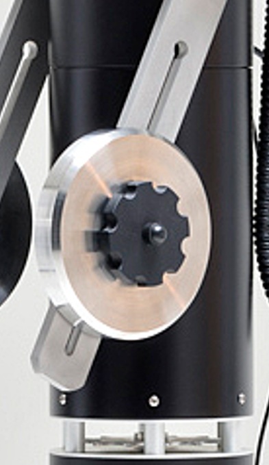
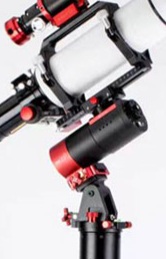

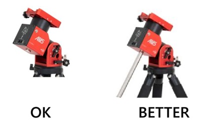


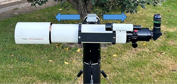
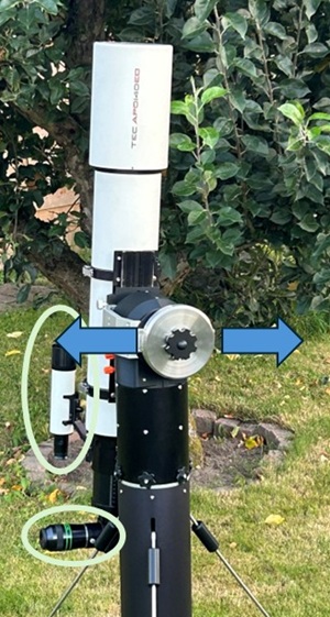


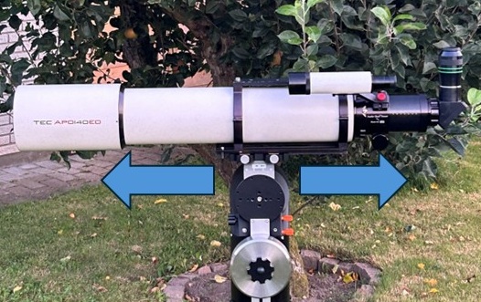
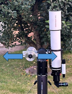
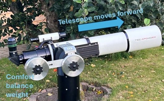
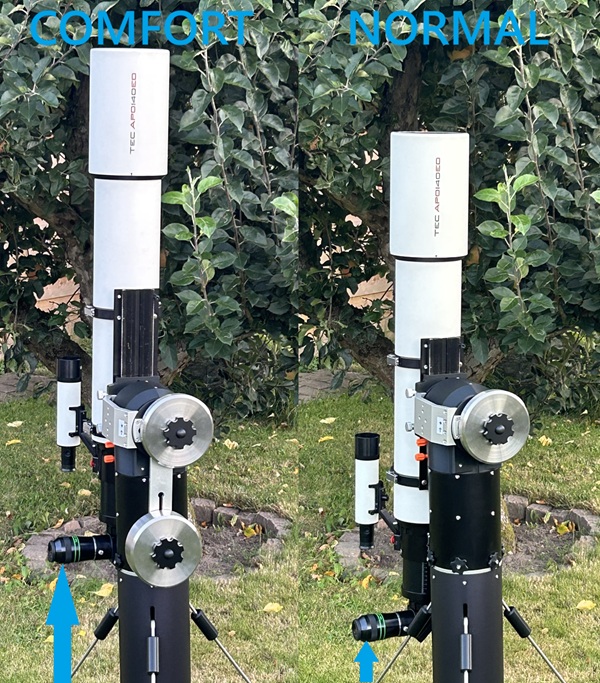
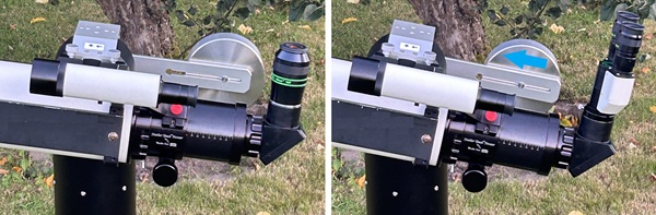

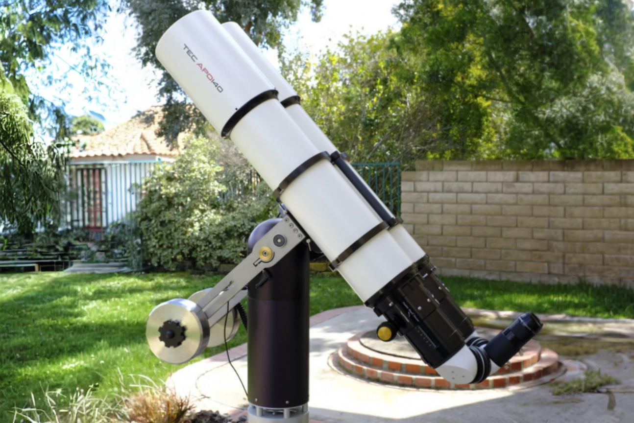
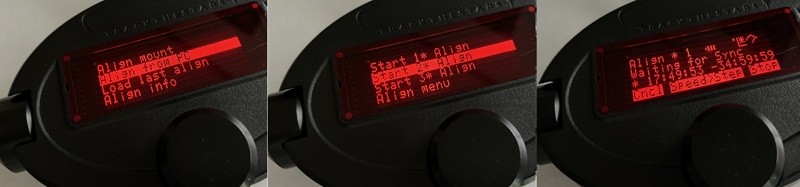
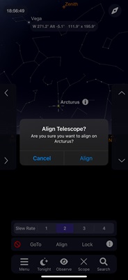
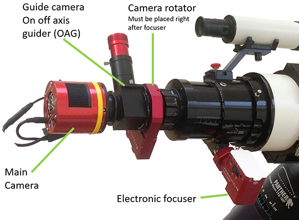
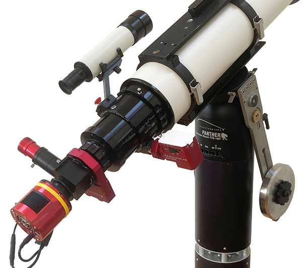
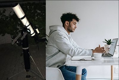
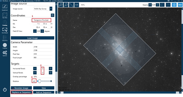
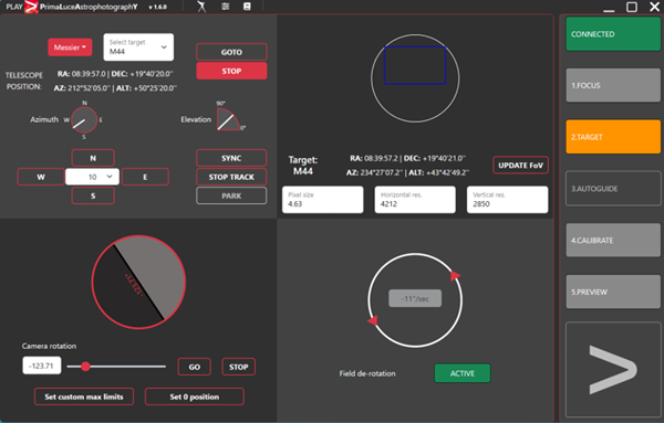
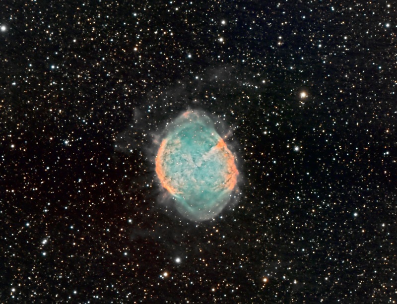
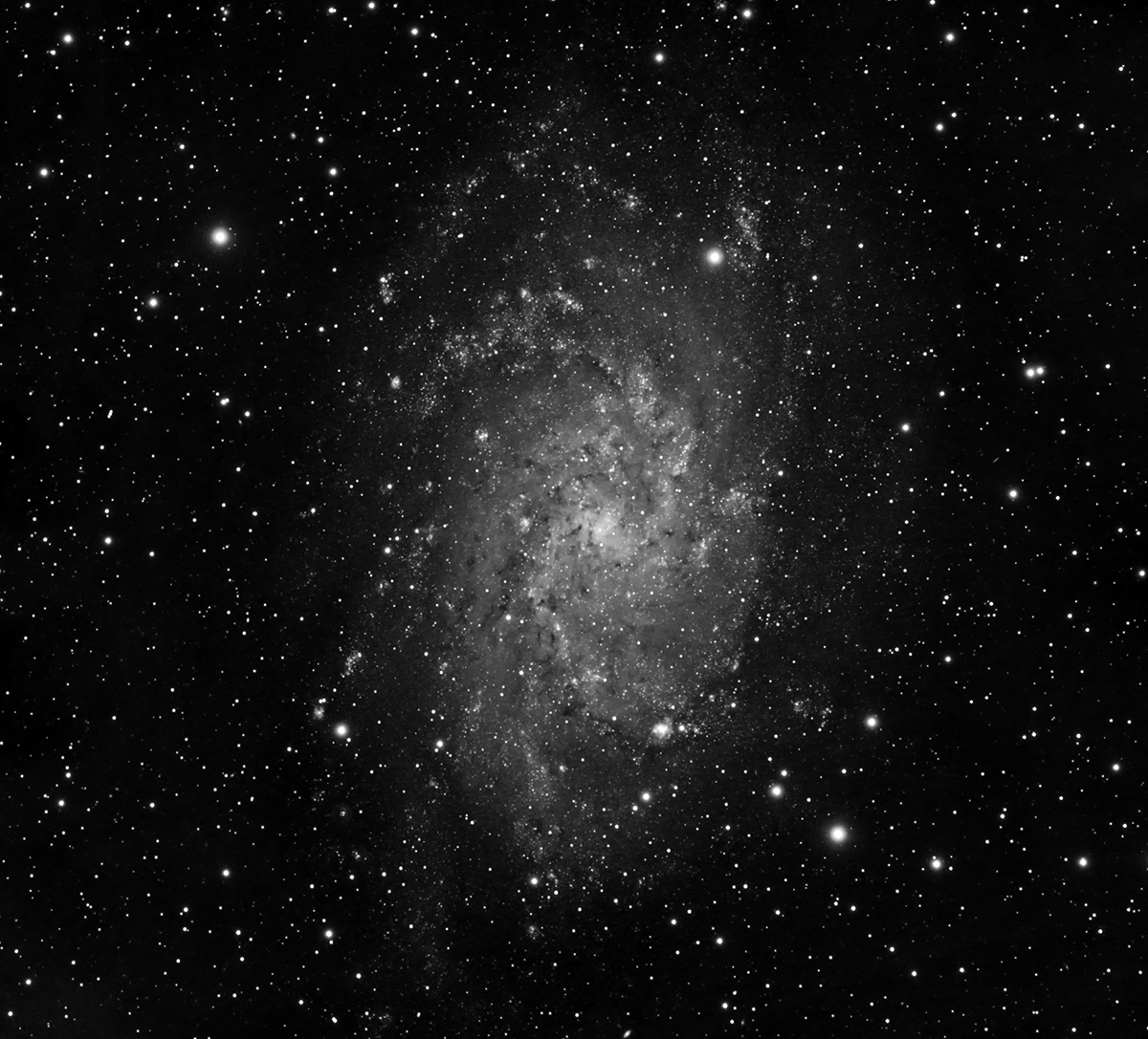
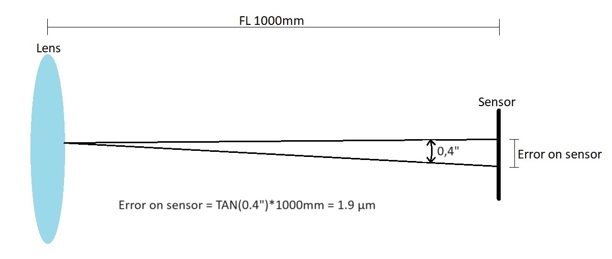
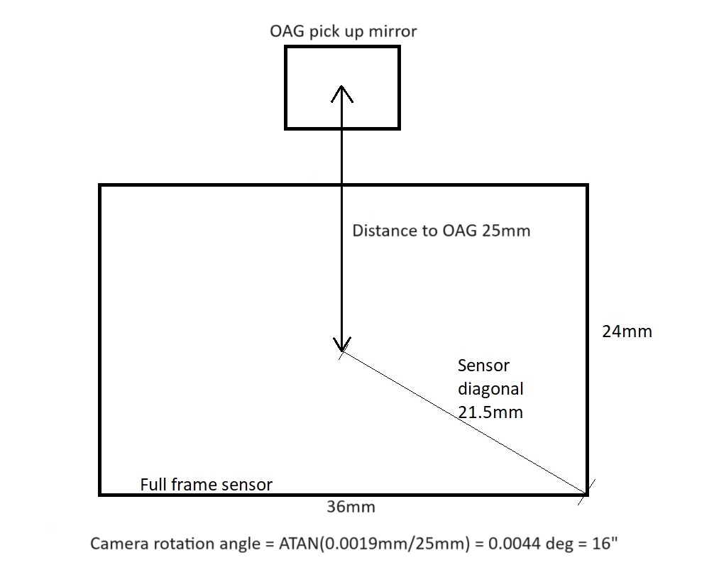
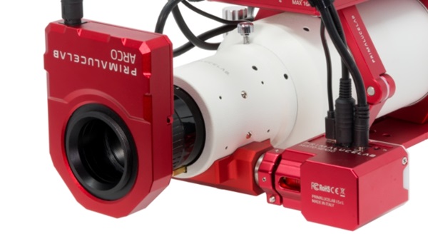
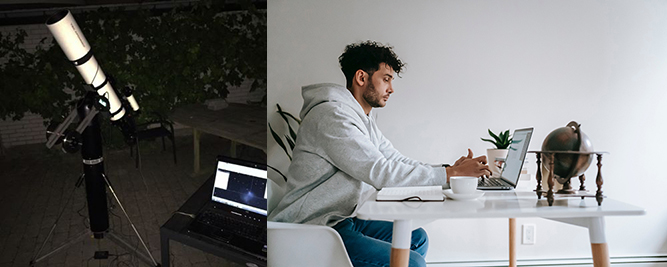
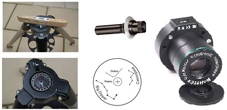
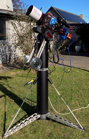
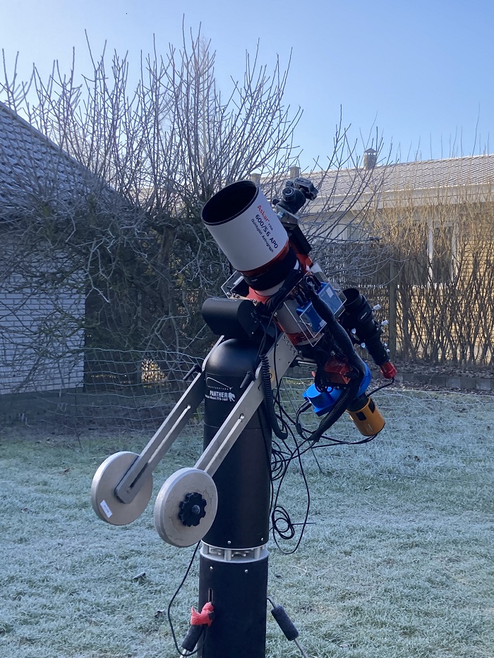
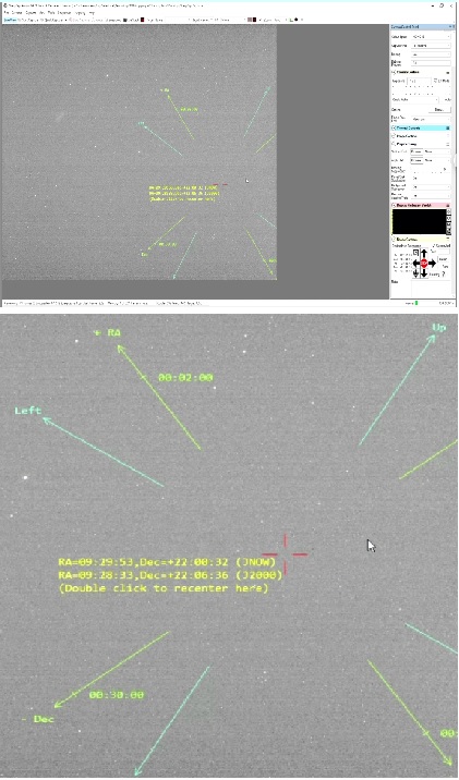
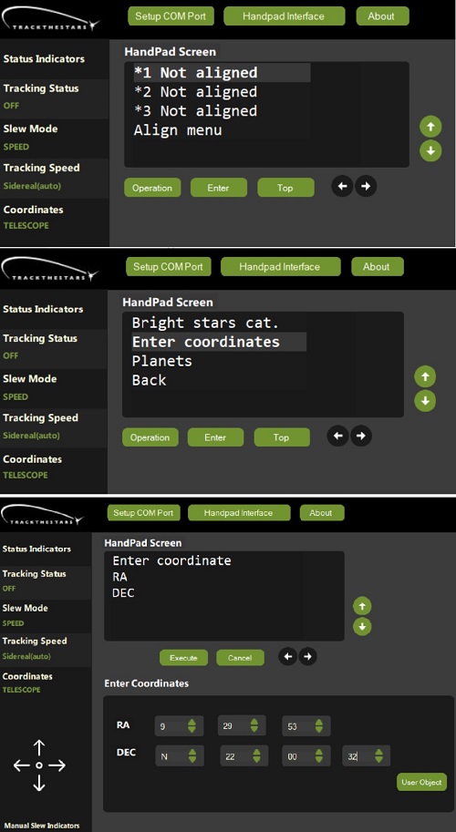
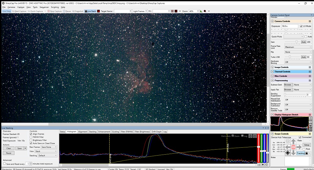
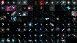
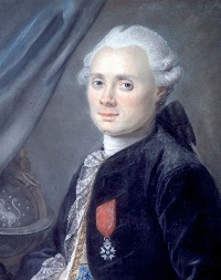
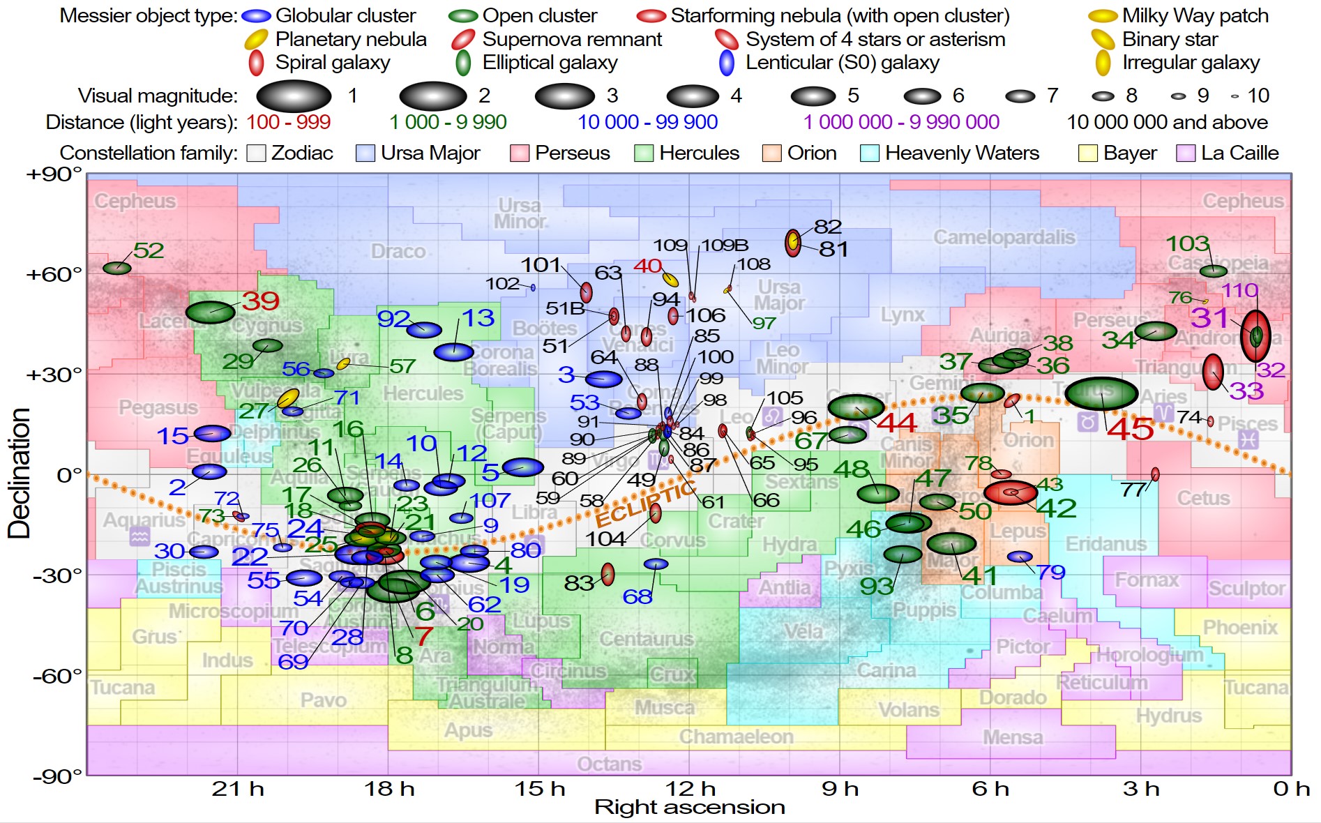
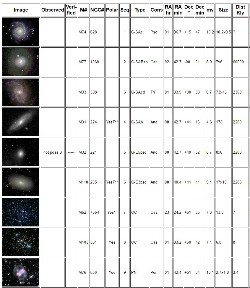
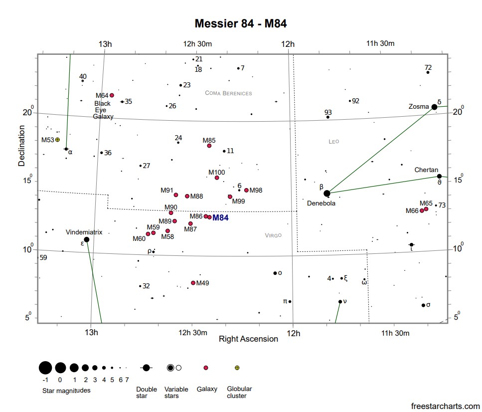
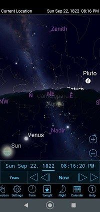
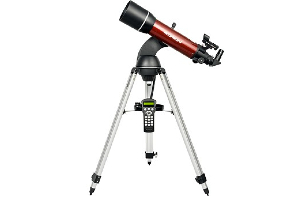
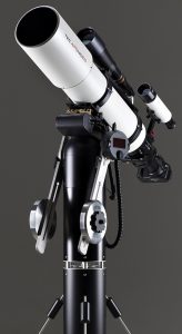
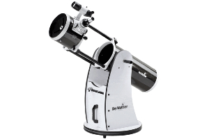
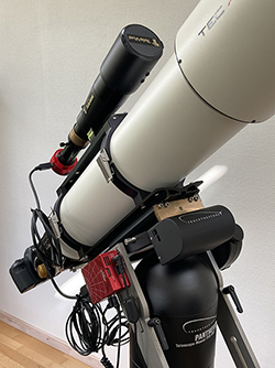
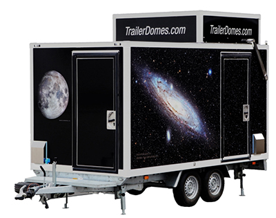
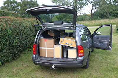
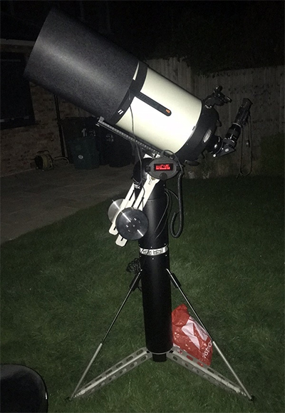
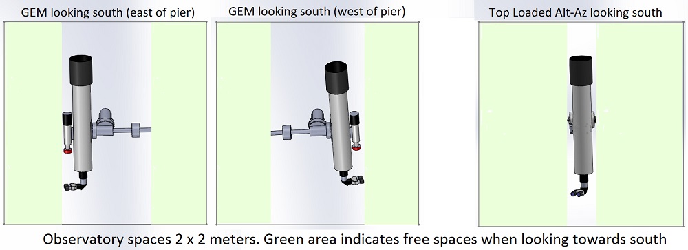
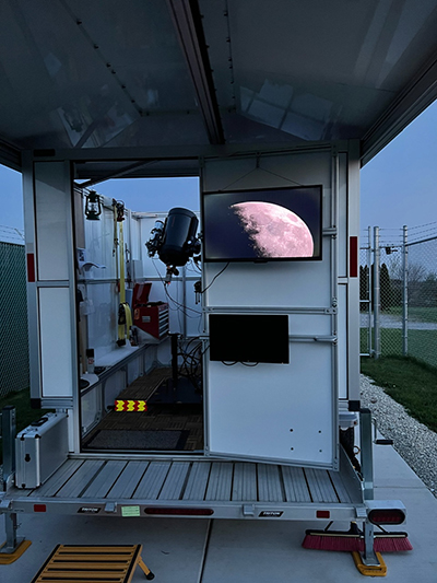
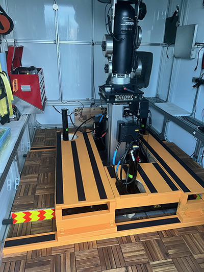
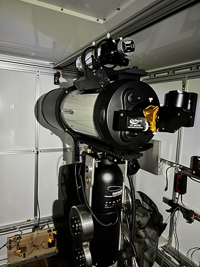
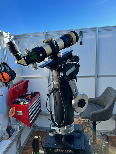
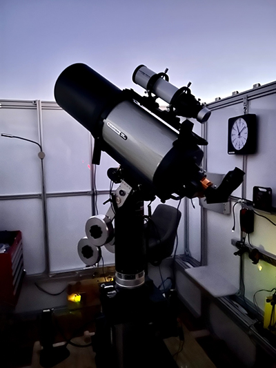
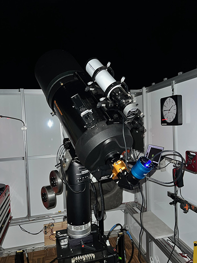
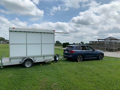 The whole thing can be towed behind my SUV but the next project is to add a nose-cone to the front of the trailer. That big flat surface halves the gas mileage I get.
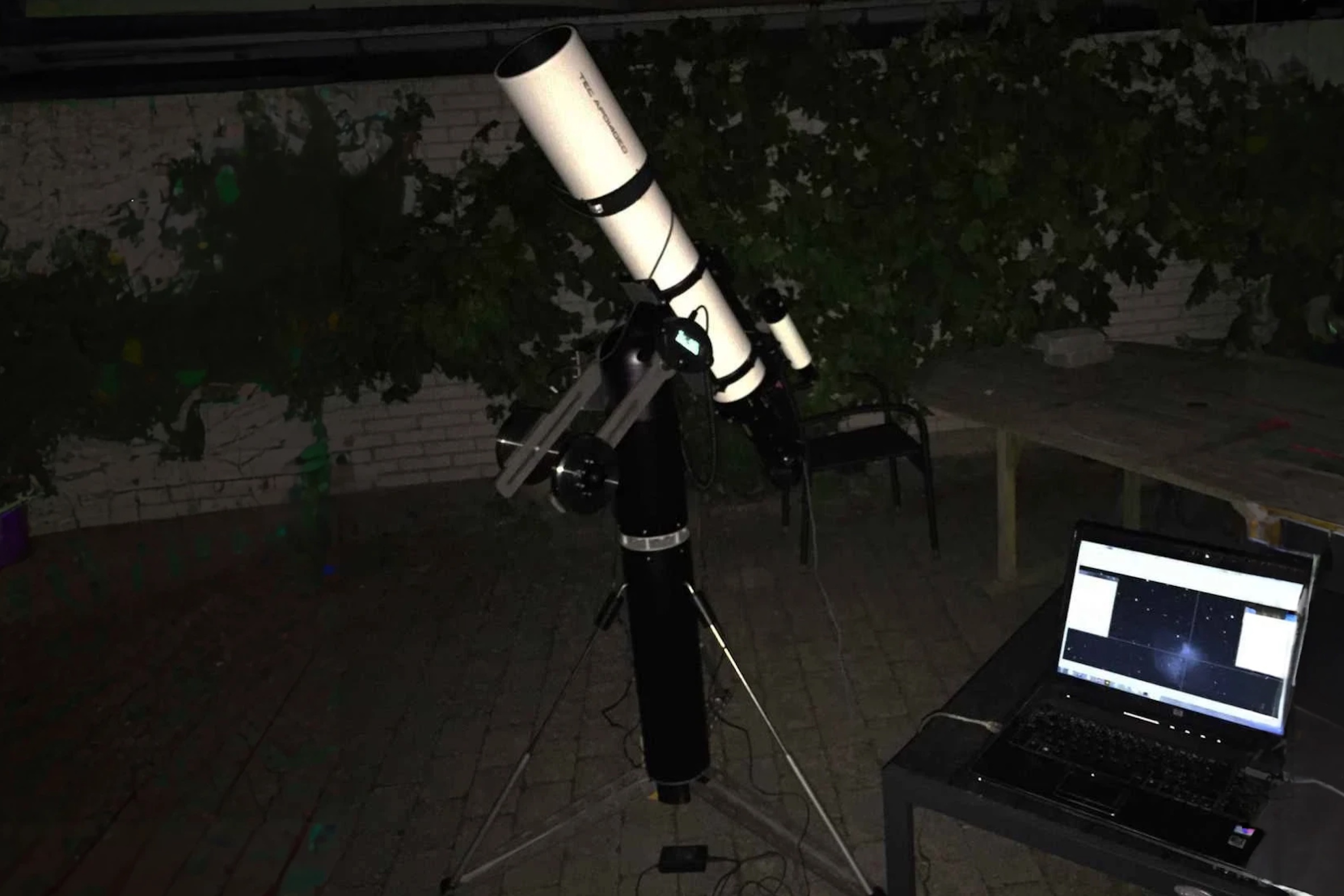
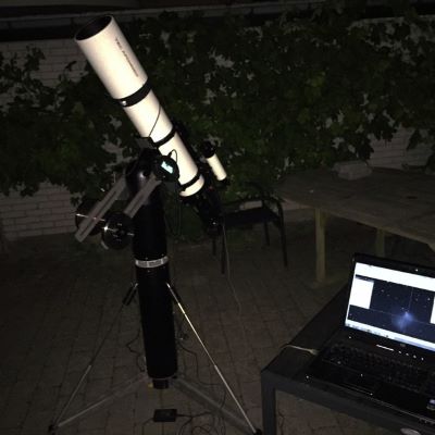
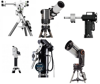

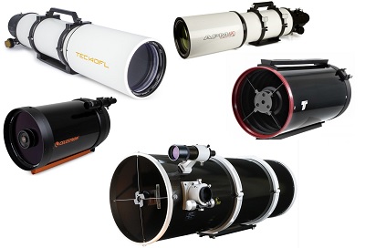
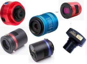
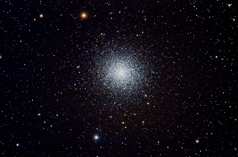
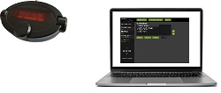
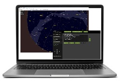
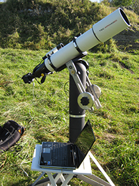
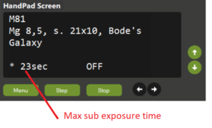
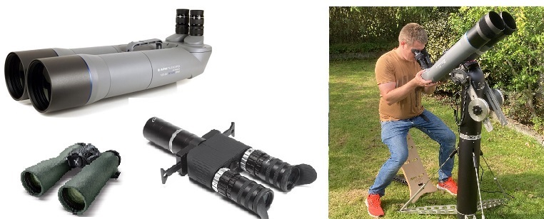
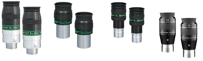
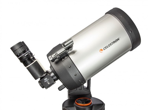
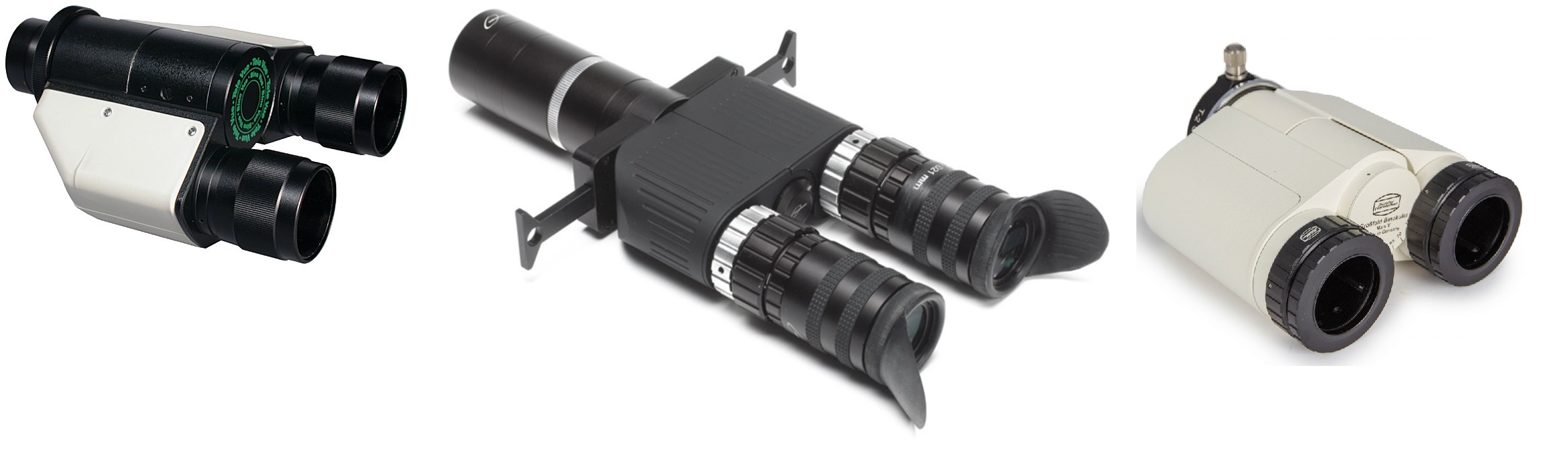 Examples of very good Bino Viewers are
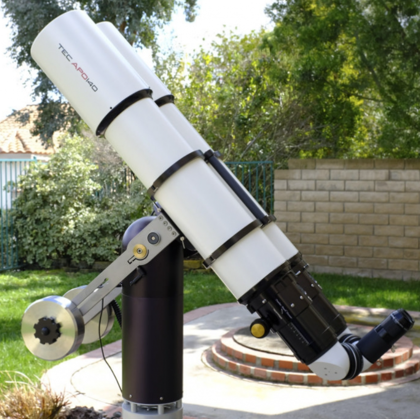
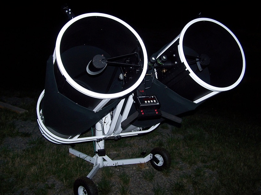
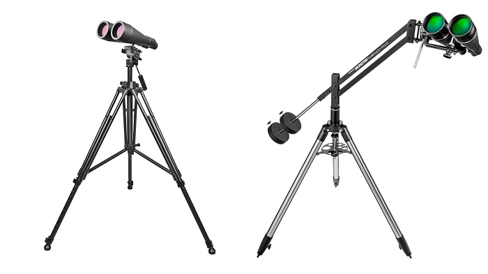
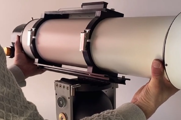
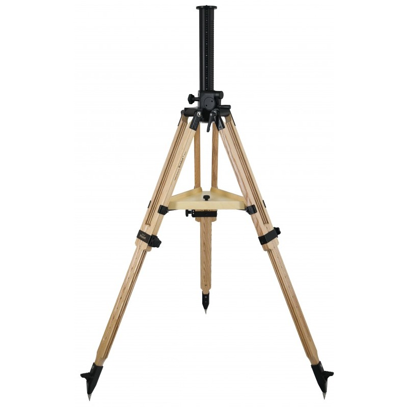
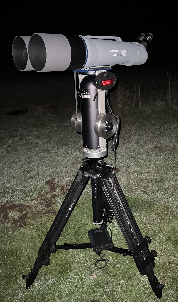
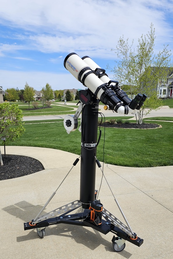
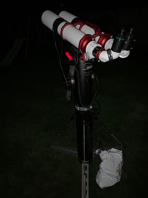
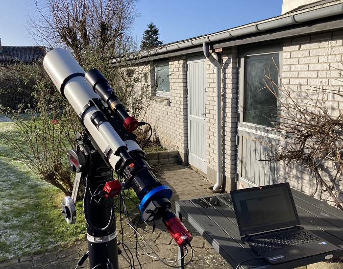
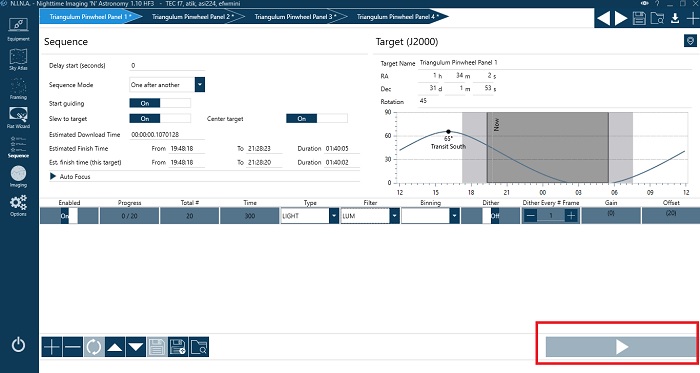
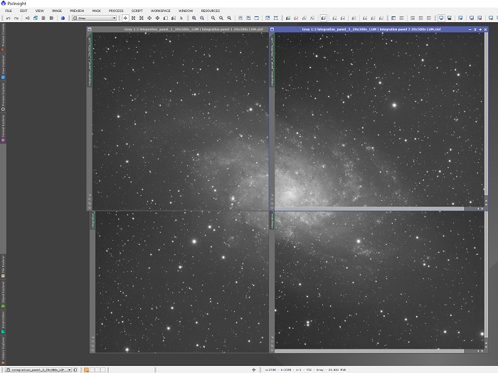

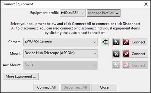
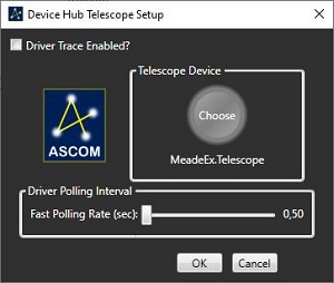
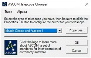
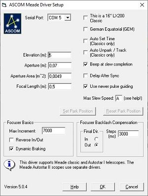


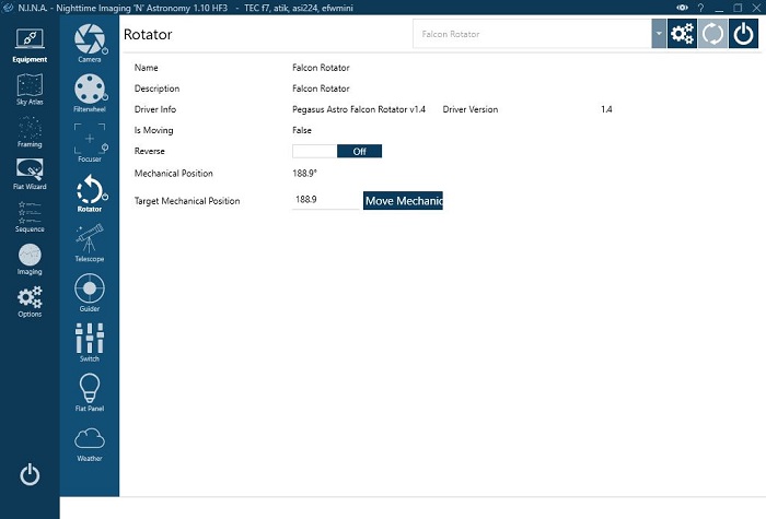

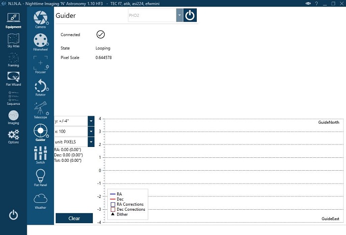
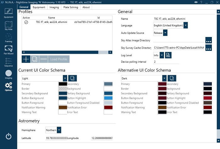

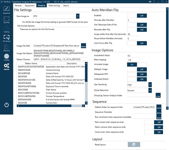
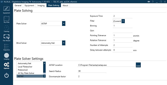

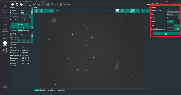
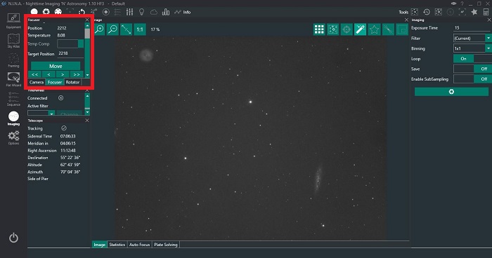

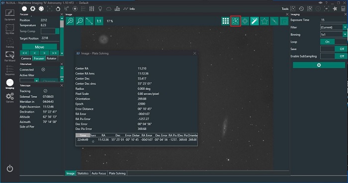
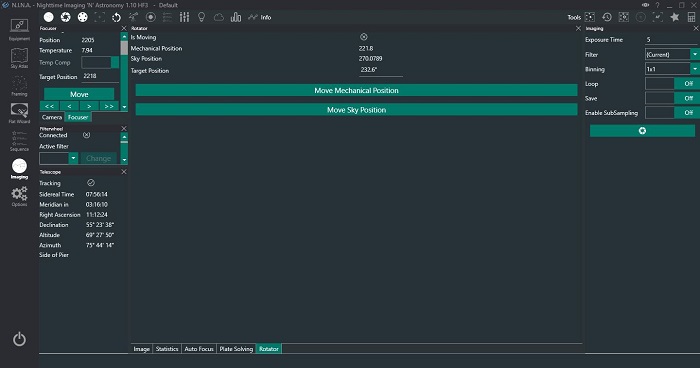
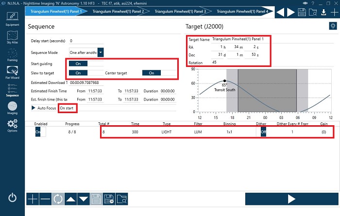
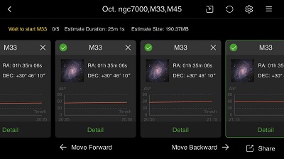

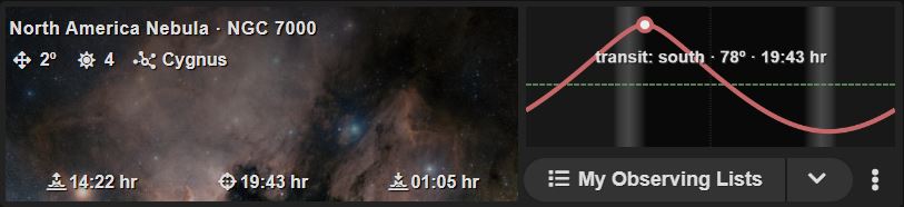
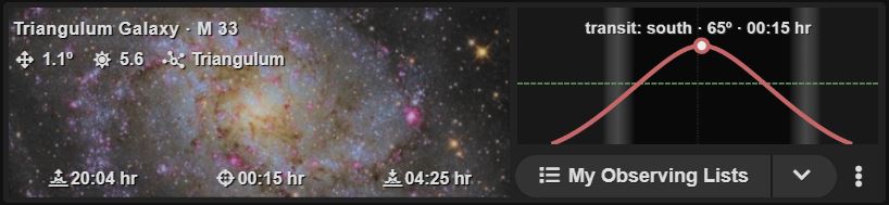
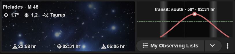
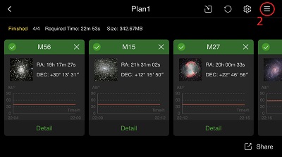


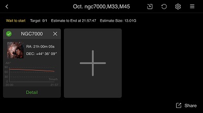
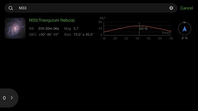
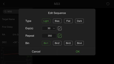
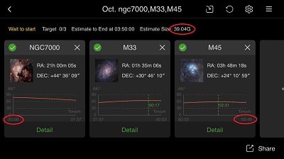
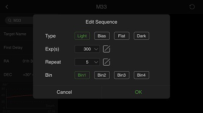
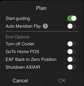
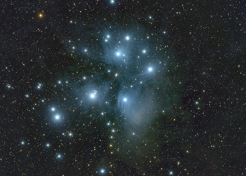
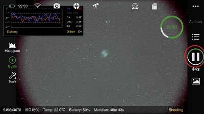
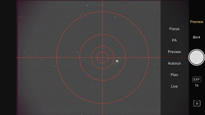
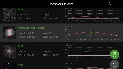
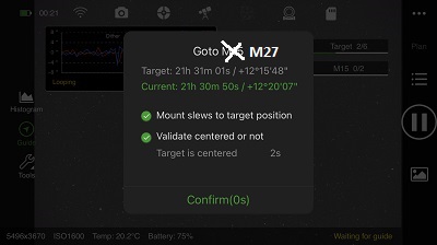
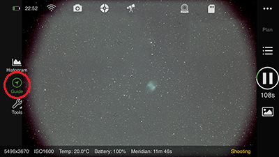
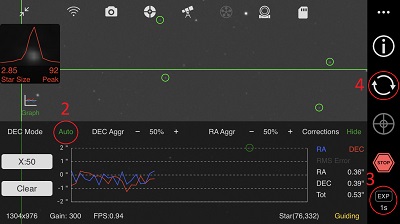
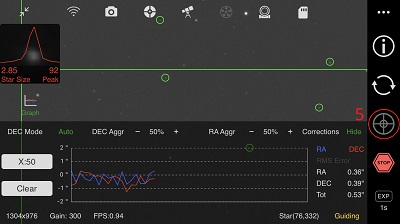
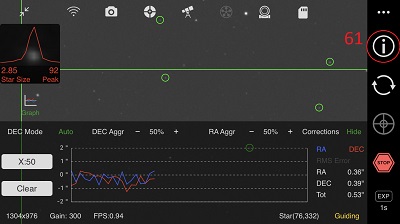
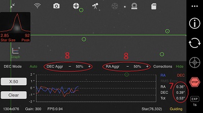
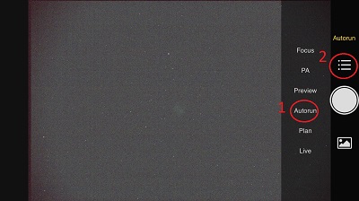
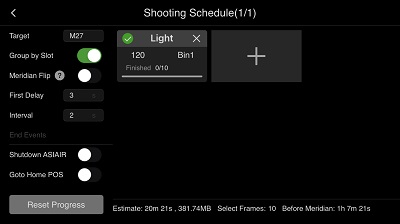
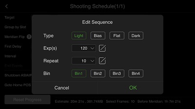
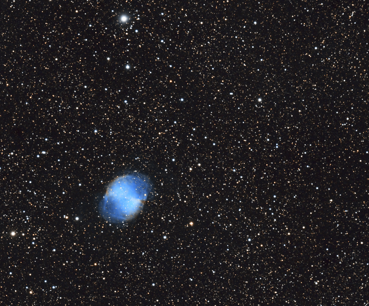
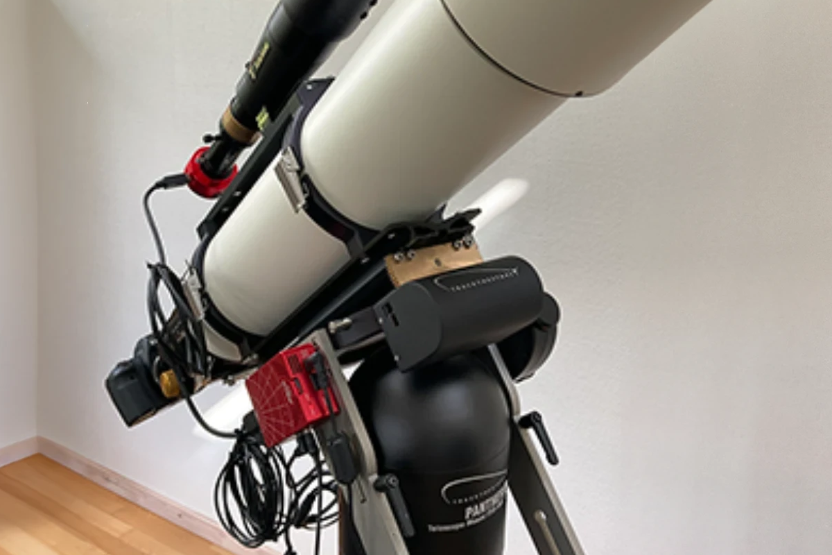
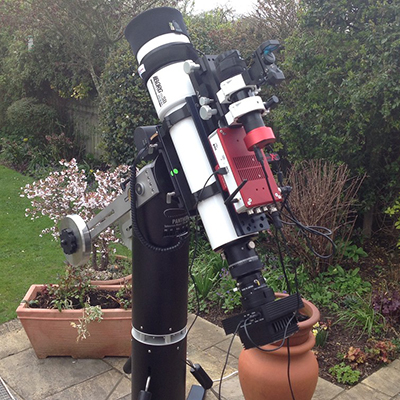
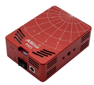
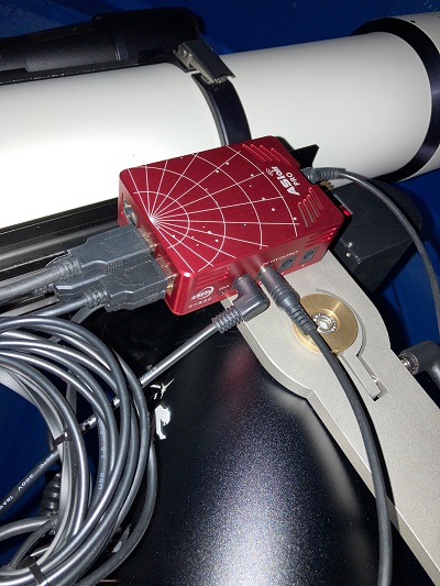
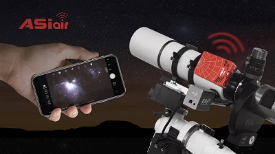
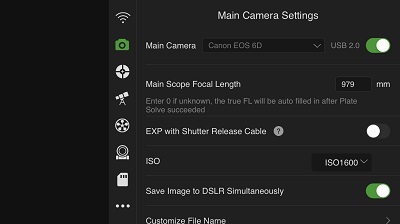
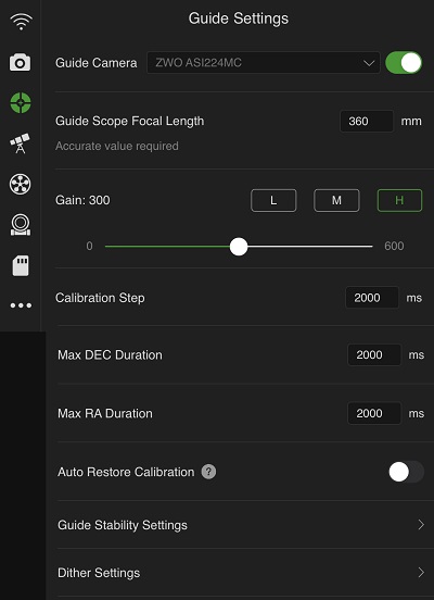
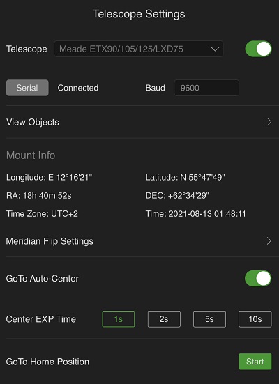
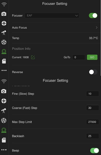
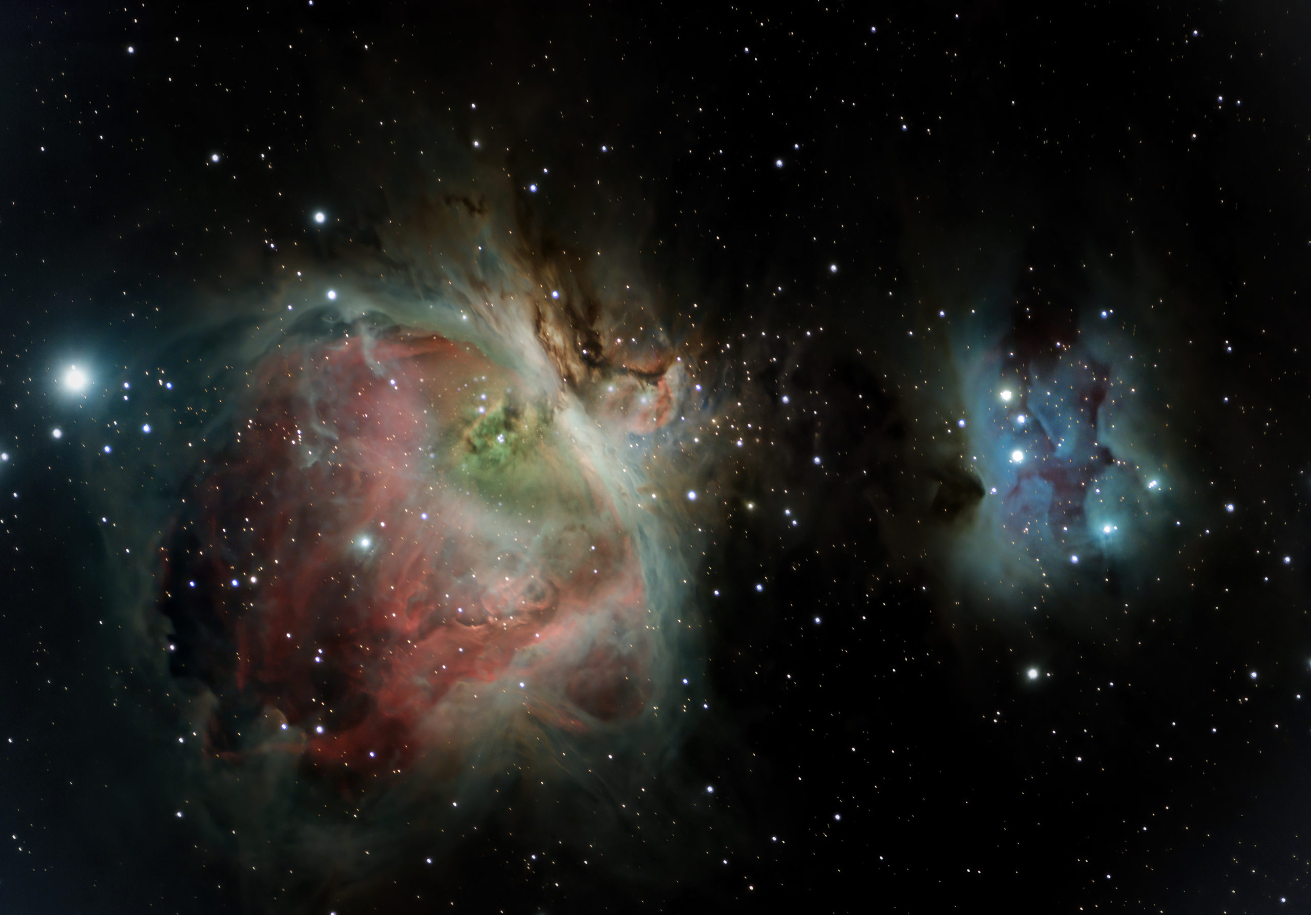
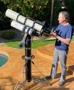 In the autumn of 2020 I noticed quite a few great astrophotos on Instagram from @azastroguy. All the images were taken with a